EE Summer School - Lab 1
Introduction
In today’s laboratory we will build a pulse oximeter system using the provided kits and lab equipment. This will involve practical skills such as circuit design and prototyping, soldering, and PCB (Printed Circuit Board) assembly.
To begin, we will first develop the necessary skills by drafting a simple circuit, selecting suitable components, and soldering.
Intro to Electronics
The following sections should help provide the necessary background theory required to complete these lab exercises.
Ohm’s Law
Ohm’s Law is a fundamental principle in electrical engineering and physics that relates the current flowing through a conductor to the voltage across it and the resistance of the conductor. It was formulated by the German physicist Georg Simon Ohm in the early 19th century.
Ohm’s Law can be stated mathematically as:
\[V = I \times R\]where:
- V represents the voltage (measured in Volts, V)
- I represents the current (measured in Amperes or Amps, A)
- R represents the resistance (measured in Ohms, $\omega$)
Voltage is measured as a difference in potential (or charge) between two points on a circuit. Current is the rate at which charge moves through a conductor. Resistance is how difficult it is for current to flow.
According to Ohm’s Law, the voltage across a fixed resistance is directly proportional to the current flowing through it.
A simple LED circuit
An LED (Light-Emitting Diode) is a semiconductor device (or component) that emits light when an electric current passes through it.
The simplest LED circuit requires only a few components, as shown in .

This circuit is made up of three key components:
- Power Supply: The power supply provides the voltage across the LED circuit. It can be a battery, a DC power supply, or any other appropriate power source. This voltage will be split between the components in the rest of the circuit.

- LED: LEDs must be chosen based on the circuit requirements, considering factors such as colour and brightness. LEDs have two leads, as shown in . The longer one is called the anode (+) and the shorter one called the cathode (-). The anode is typically connected to the positive terminal of the power supply.

- Current limiting resistor: LEDs have almost no resistance when plugged in the correct way. To limit the current flowing through the LED, and prevent it from burning out, you must therefore include a current-limiting resistor in the circuit.
The resistor value, $R$, depends on the LED’s forward voltage, $V_f$, (which is effectively the voltage that is consumed by the LED) and the desired current, $I$. You can use Ohm’s law to calculate the resistor value.
The formula for this is:

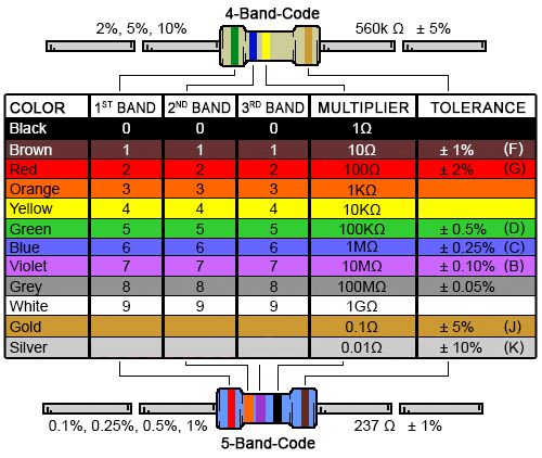
Resistors are typically marked with coloured stripes so that people can tell what resistance they are designed to have. These stripe colours follow a standard, shown in . The multiplier is multiplied with the two or three digit number denoted by the first two or three stripes to produce a final resistance value.
Breadboards
Breadboards are solder-less prototyping boards that engineers can use to quickly test circuit designs. The legs of components and wires can be poked through the holes on the Breadboard. These holes are internally connected in a simple grid pattern, allow engineers to form circuits by carefully selecting where they plug components into.

shows how the holes are commonly connected within the Breadboard. It should be noted, however, that sometimes the rails on the side are split in half, denoted by a divided line down the side.
Ex. 1 - Building an LED circuit
We will now apply the theory above to design, build and test a simple LED circuit. This will help provide some of the experience required when building the pulse oximeter.
Selecting a suitable resistor
The LEDs that we are going to use are defined in their datasheet as having a forward voltage of $V_f = 2.1$ Volts. The datasheet also tells us that ideal current that these LEDs are designed to support is around $I = 20$ mA.
Using this information, along with the information provided above, determine the ideal resistance for the current limiting resistor. You can assume that we will use a 5 Volt power supply for this circuit.
Now that you have chosen your ideal resistor size, find one of the demonstrators and ask them for the resistor you have chosen.
With your resistors selected, we will now attempt to build the circuit shown in .
Building the circuit on Breadboard
Use the information provided in the introduction section and attempt to build the circuit described in .
You may need some additional wires to achieve this. You will find these provided along with the power supply and breadboard on each of the lab desks.
Larger resistances
You have hopefully now seen what happens when the resistor is correctly sized to limit for the LED. Based on what you now know, what do you think would happen if you swapped the resistor out for a much larger resistance?
Once you have a hypothesis, switch the circuit off and swap the resistor for the larger resistance that you were also given to see if your theory is correct.
The next task requires a bit of a conversation with staff before you can fully dive in. Once you have completed the tasks above, let one of the demonstrators know and tell them what it is that you have learned today so far.
Ex. 2 - Analyzing a Pulse Oximeter
As mentioned in the introduction, you will be building a pulse oximeter kit. Pulse oximeters obviously need some more complex components than just LEDs, resistors and power supplies. When engineers design a circuit, they typically produce a schematic which tells the reader how the components connect together. The schematic for todays pulse oximeter is shown below in , though it may also be viewed as a separate PDF file.
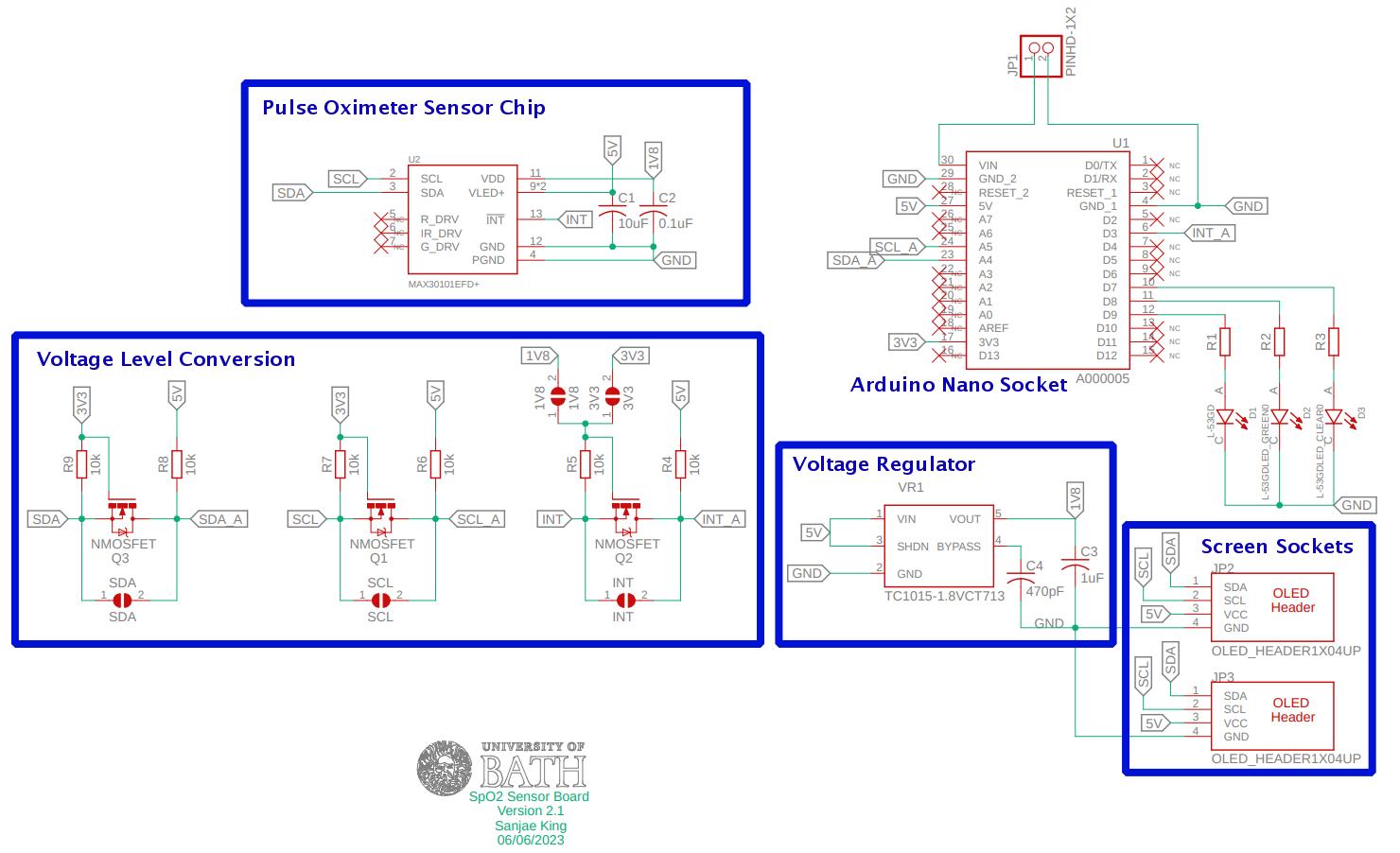
This schematic has lots of elements that tell the reader something about the design. These key elements are:
-
Components: Each electronic component in the circuit is represented by a specific symbol. The symbols represent different types of components , such as resistors, capacitors, diodes, transistors, ICs, etc. Each symbol usually has additional information, such as a component value or part number, associated with it.
-
Pins: Component symbols often have pins or terminals that represent the electrical connections. These pins are often numbered or labelled and are used to indicate how components are connected to the rest of the circuit.
-
Power and Ground Symbols: Power and ground symbols are often used to represent where the power supply connections and the reference point (or ground) are connected to other parts of the circuit. This is often done in multiple places because so many connections all going to the place would make the schematic hard to read.
-
Part Numbers: Each component in the schematic is assigned a unique designator, such as R1, C2, U3, etc. These help identify and reference components in the circuit.
-
Annotations and Notes: Schematics may include annotations, notes, or additional text to provide further information or clarify specific aspects of the circuit design.
-
Design Rules and Constraints: Schematic design tools also allow designers to define design rules and constraints, such as trace width, clearance, and other parameters, which help ensure the design meets electrical and manufacturing requirements. These are sometimes included on the schematic, or provided as a separate constrains file.
Looking again at the schematic, you will notice that there are no resistance values listed for R1, R2 and R3. There are also some components that wont actually be fitted when constructing the circuit. This is because engineers often add redundancy to their designs to allow modifications or support different operation after manufacture.
Calculating resistor sizes
In Exercise 1, you have previously seen how to size resistors to ensure that the LEDs operate as intended. In this case, we have three different LEDs, so we must check the datasheet for each to ensure that we select the correct resistance value.
Review the datasheets for each of the following LEDs and identify the typical forward voltage and test current for each.
You will notice that the datasheet for the Bi-Polar LED contains two different typical forward voltage levels, one for each color. In this case you will want to use the lower of the two forward voltages as that would ensure that the target current is never exceeded. This will mean that the other color will be slightly dimmer, but it should be an imperceivable difference.
Now that you have the data for each LED, calculate the ideal current limiting resistance for each LED if the voltage provided is 5V.
Now that we know what resistor sizes you will need, go and ask a demonstrator for a Pulse Ox kit.
Ex. 3 - Building the Pulse Oximeter
Inside the kit, you will find all the parts needed to build a fully functional pulse oximeter. This will involve soldering and careful placement of components on the PCB. A brief summary of soldering is shown below in .

The PCB, or Printed Circuit Board, is used to hold and connect the components. In this case we have designed and assembled a PCB for you, and it should look like the one in .
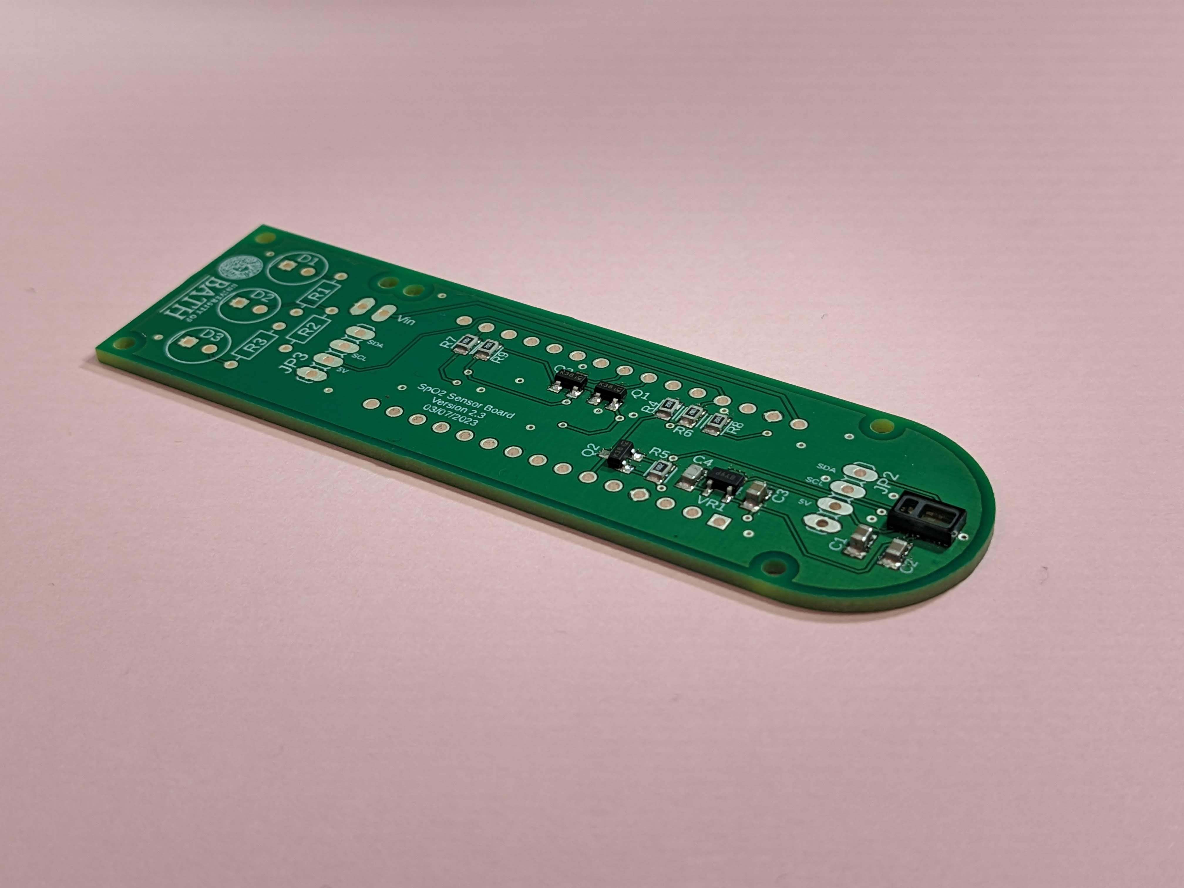
You may notice that there are already some very small components that have been added to the board. We will be adding additional components to finalise the circuit.
Adding the Resistors
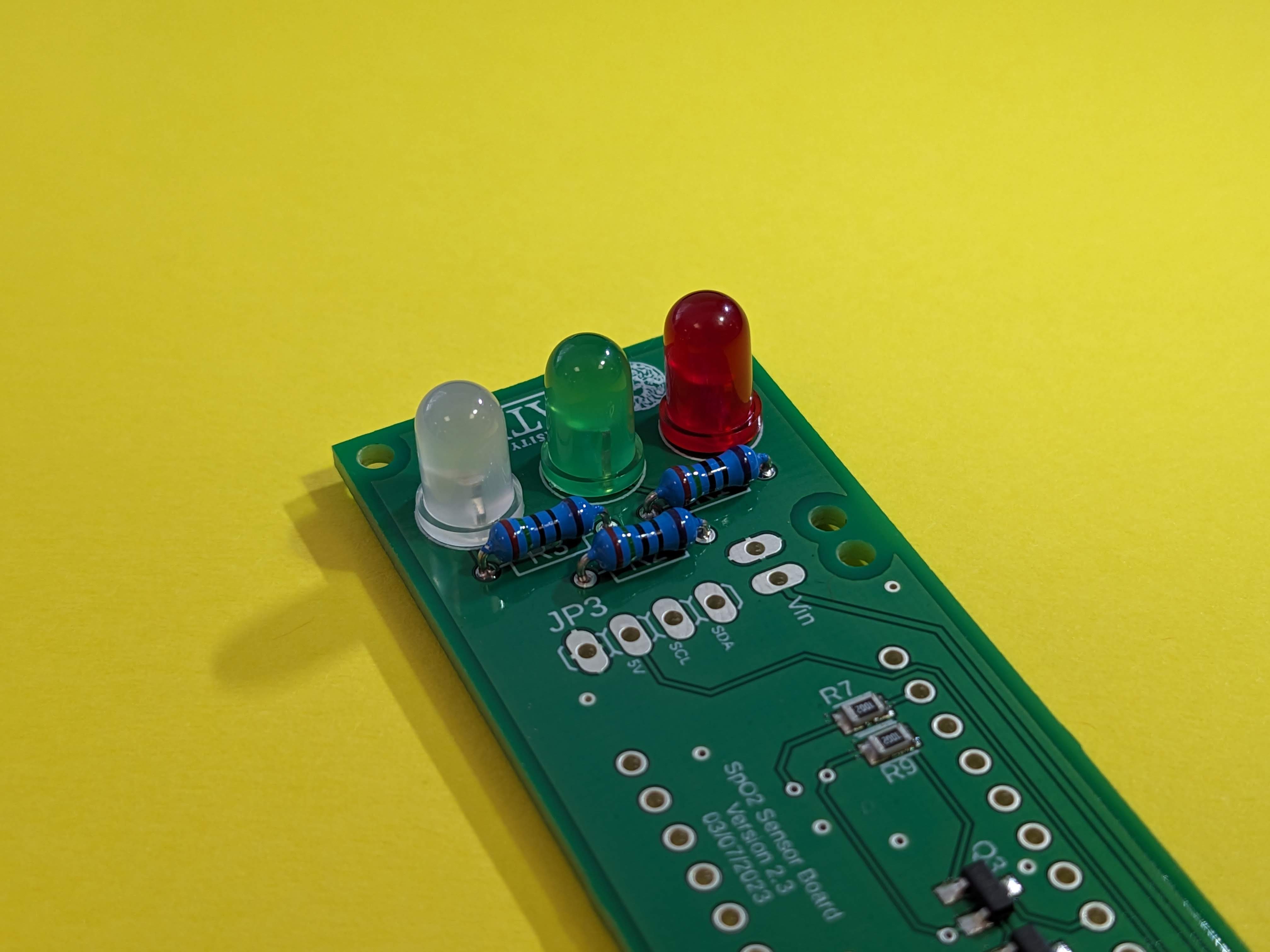
Looking closely at the board, you will nice that there are three boxes labelled R1, R2 and R3. These boxes have holes for resistor legs on either side. Bend the legs and feed them through the holes so that the board matches the one shown in . Make sure not to trim the legs yet, we will only do that once the resistors have been soldered into place!
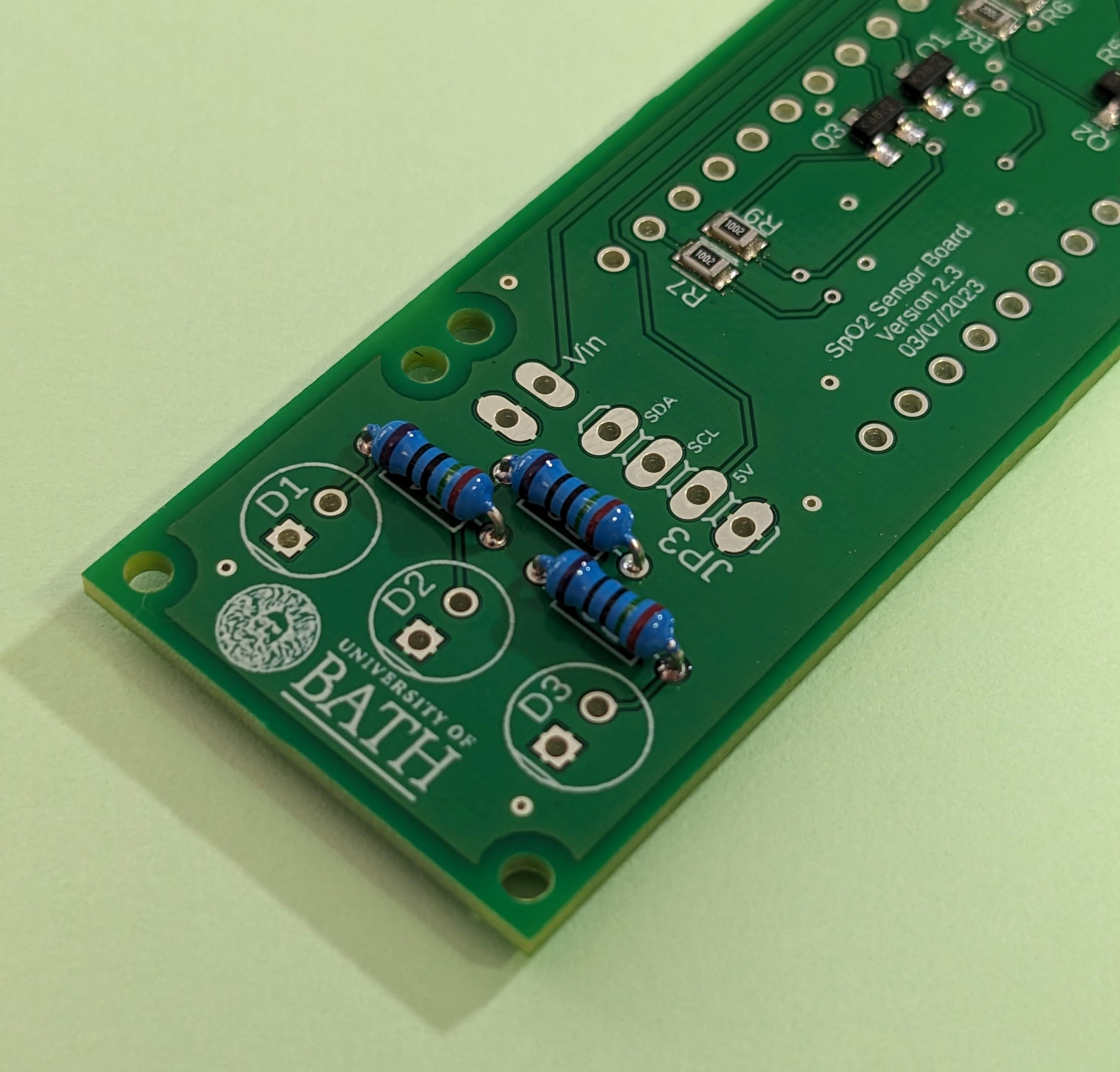
Then flip the board over and solder the legs to the pads on the bottom side of the board, before clipping the legs short. An example of what this should look like (with a few additional components added) is shown in .
Adding the LEDs
We will now add the LEDs to the board. Remember, these are polarized devices and therefore need to be added to the board in the correct orientation.
The orientation of the LEDs may be determined using the while lines (known as Silkscreens) on the top side of the board. Looking at D1, D2, and D3, you will notice that they are denoted by a circle with a line in one side. This line is designed to align with the flat edge of the LED package. Additionally, you will notice that one of the holes has a square pad, which on this occasion should house the shorter of the two LED legs.
Each LED must be placed in the correct location as follows:
- D1: Red LED
- D2: Green LED
- D3: White Packaged Bi-Polar LED
Poke each LED through the holes listed above, making sure to match the package orientation with the silkscreen. Now flip the board over and solder the LEDs into place. Once done your board should now resemble that shown in .
Sometimes, designers add something called solder shorts to a board to allow the assembler to disable or enable different parts of a circuit while they build the product. This has actually been done on this PCB too. If you flip the board over, you will notice that there are some very close-together pads labelled 1V8, 3V3, SDA, SCL and INT. Most of these we can ignore as they were included for when we were testing the board prototypes.
There is however one that we must link, and that is the 1V8 short. By linking the two pads under 1V8 with solder, we will power the pulse oximeter sensors with a 1.8 volt supply (as you can imagine, the 3V3 short would have powered the sensor with 3.3 volts, however this would be too much voltage for the sensor that is actually fitted to the board).
We call this a solder short because we are physically shorting the two points together using solder.
Adding the Headers
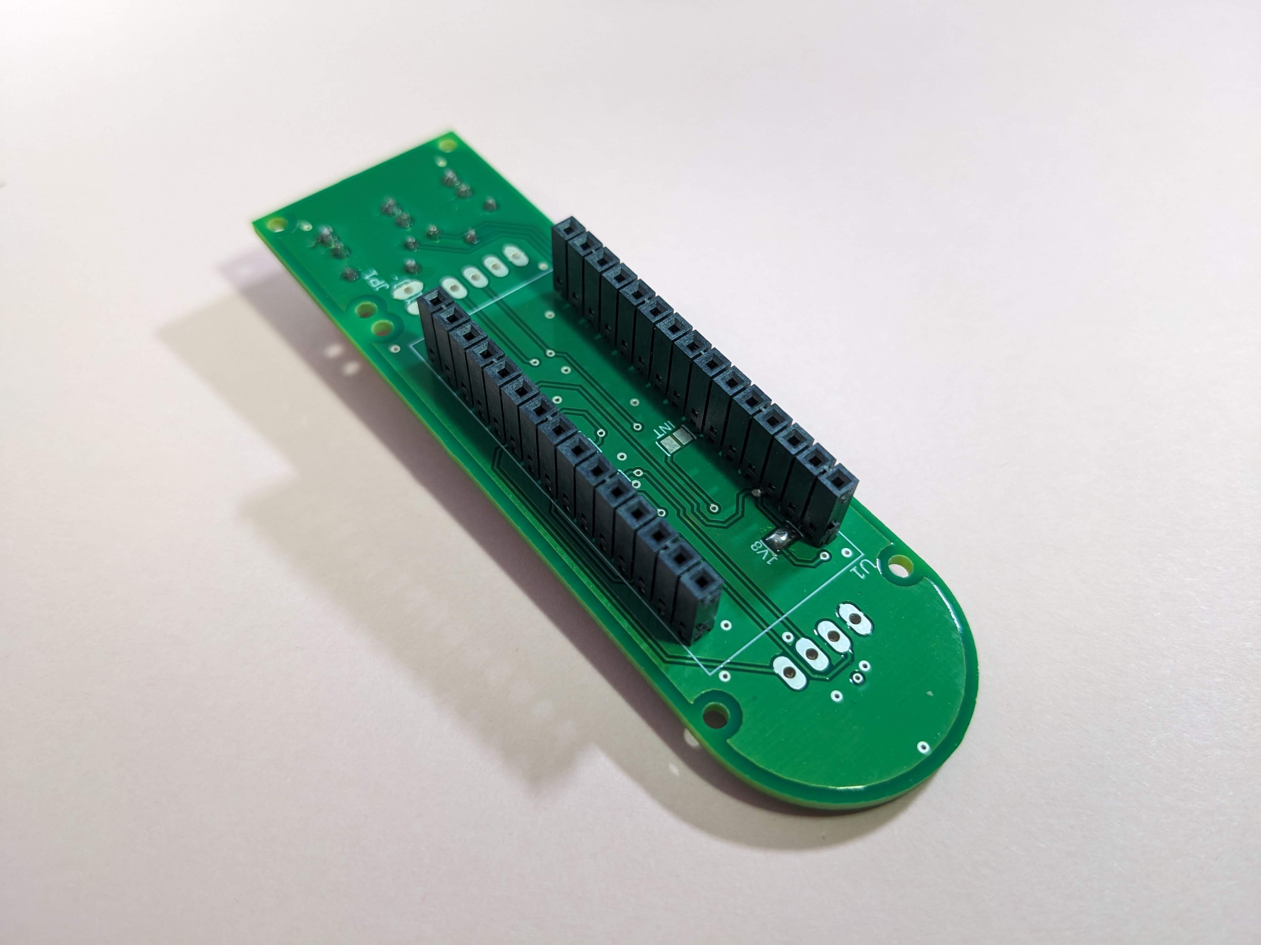
We will now add the only through-hole components that go onto the underside of the PCB - the headers. These are used to connect one circuit board to another, allowing signals and power to flow between the two. Headers have the advantage that the two connected boards can be un-connected by simply unplugging the headers. This means that boards can be easily upgraded or switched out.
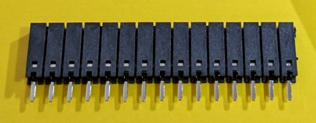
When soldering headers, it can sometimes help to first plug the headers into the other board as this ensures that the headers are aligned correctly with one another. In this case, we will do exactly that, as this will help to ensure that the Arduino Nano (the other board, shown in ) will fit smoothly into the top of the two headers.
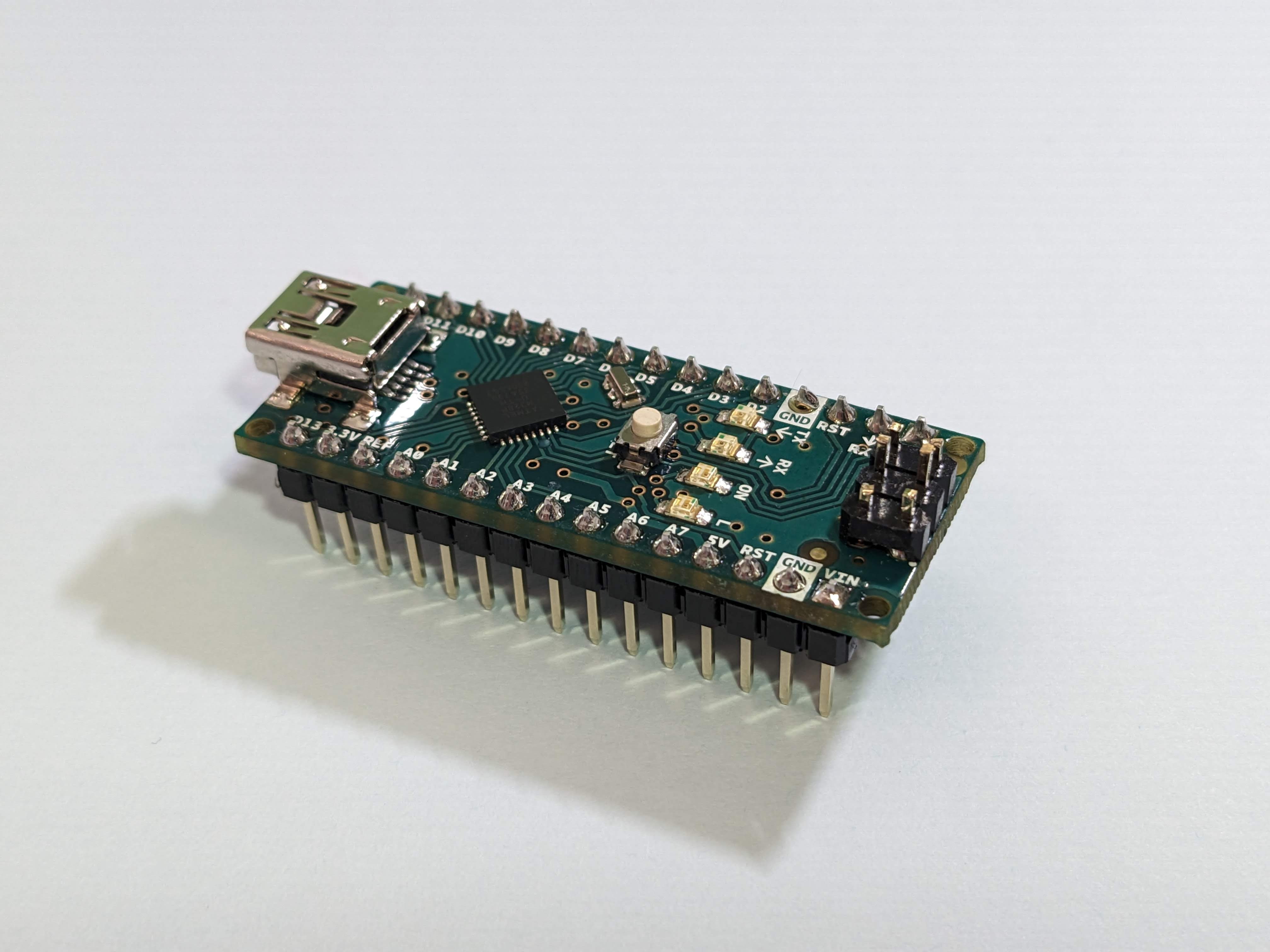
Take the Arduino Nano out of it’s box. You will notice that it has two long rows of pins, which should plug into the top of the two headers provided.
Once the headers have been fitted to the Arduino Nano, align the headers with the holes on the underside of the PCB. The USB socket on the Arduino Nano should point towards the flat edge of the PCB.
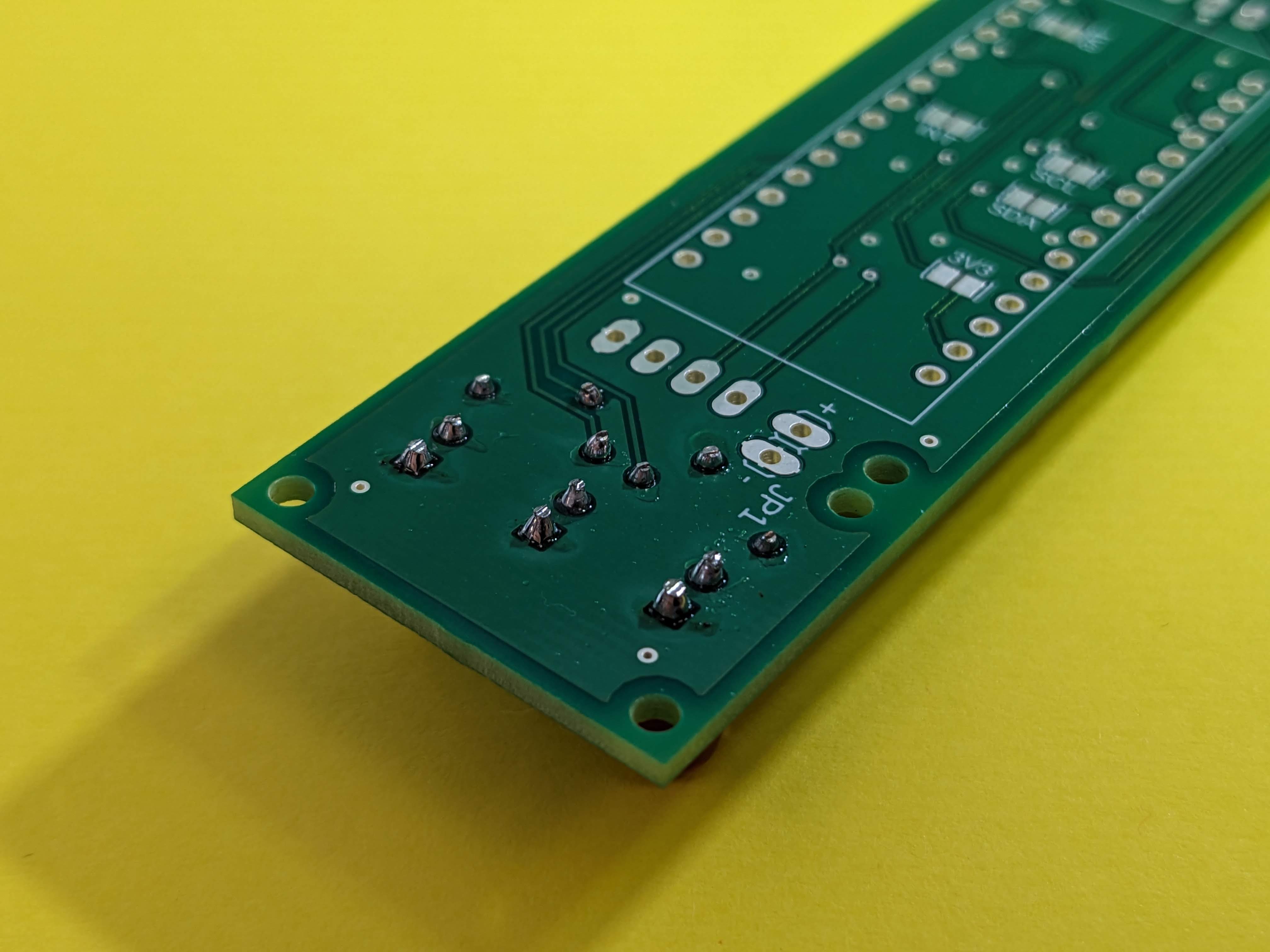
Solder the headers into place, and then unplug the Nano from the sockets. The underside of your board should now look like .
Adding the Screen
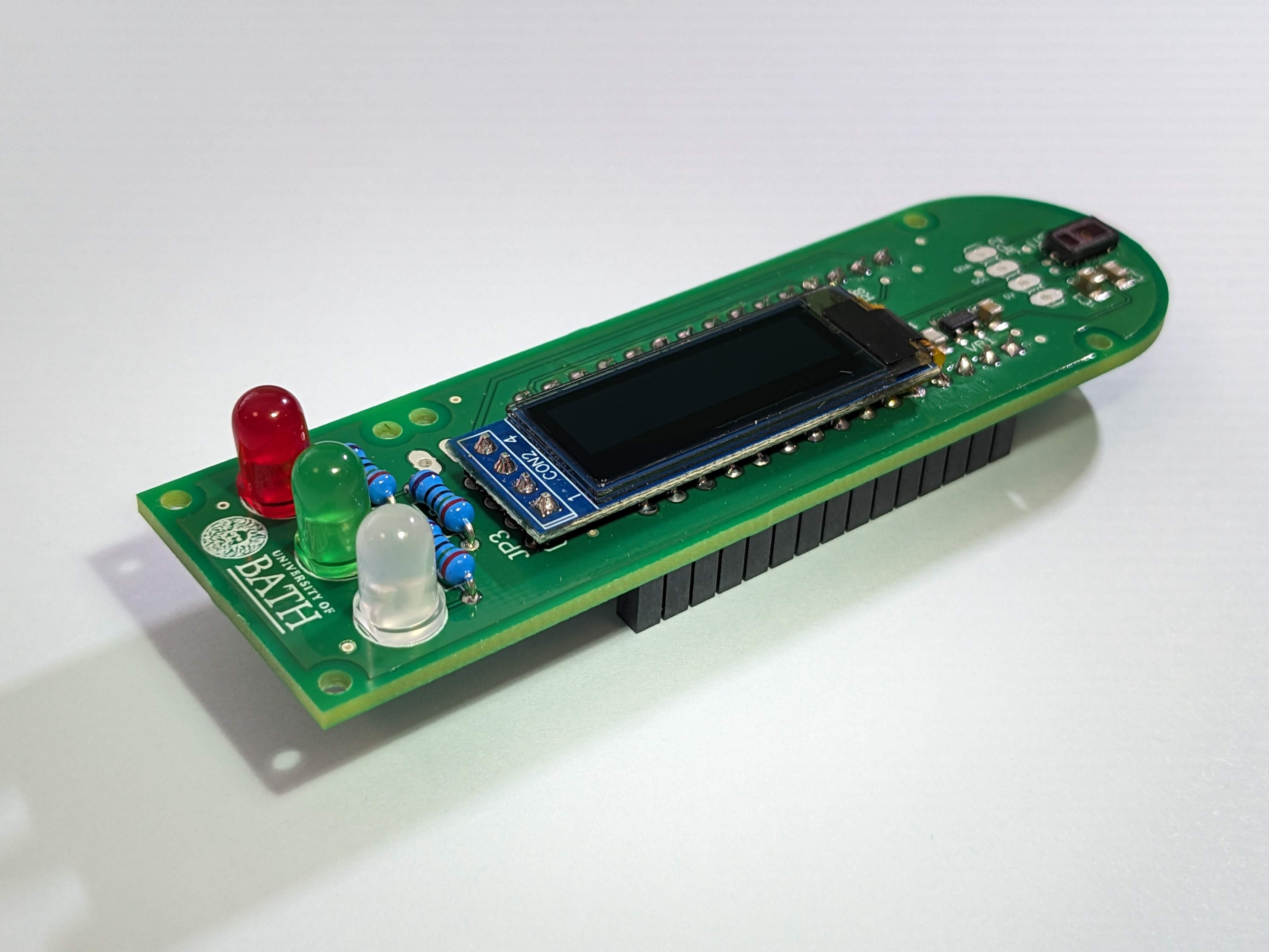
The screen is a little different to the other components. Because it has exposed components on it’s underside, we must make sure that it cannot short with anything when it is added to our PCB. To do this, we will use a dab of hot-glue from a glue gun on our PCB before quickly sliding the screen into it’s JP3 pads ready to solder it. You should use just enough glue to support the top right corner of the screen once it has been added into it’s socket. The underside of the screen should not be resting on any of the solder joints for the Arduino Nano header.
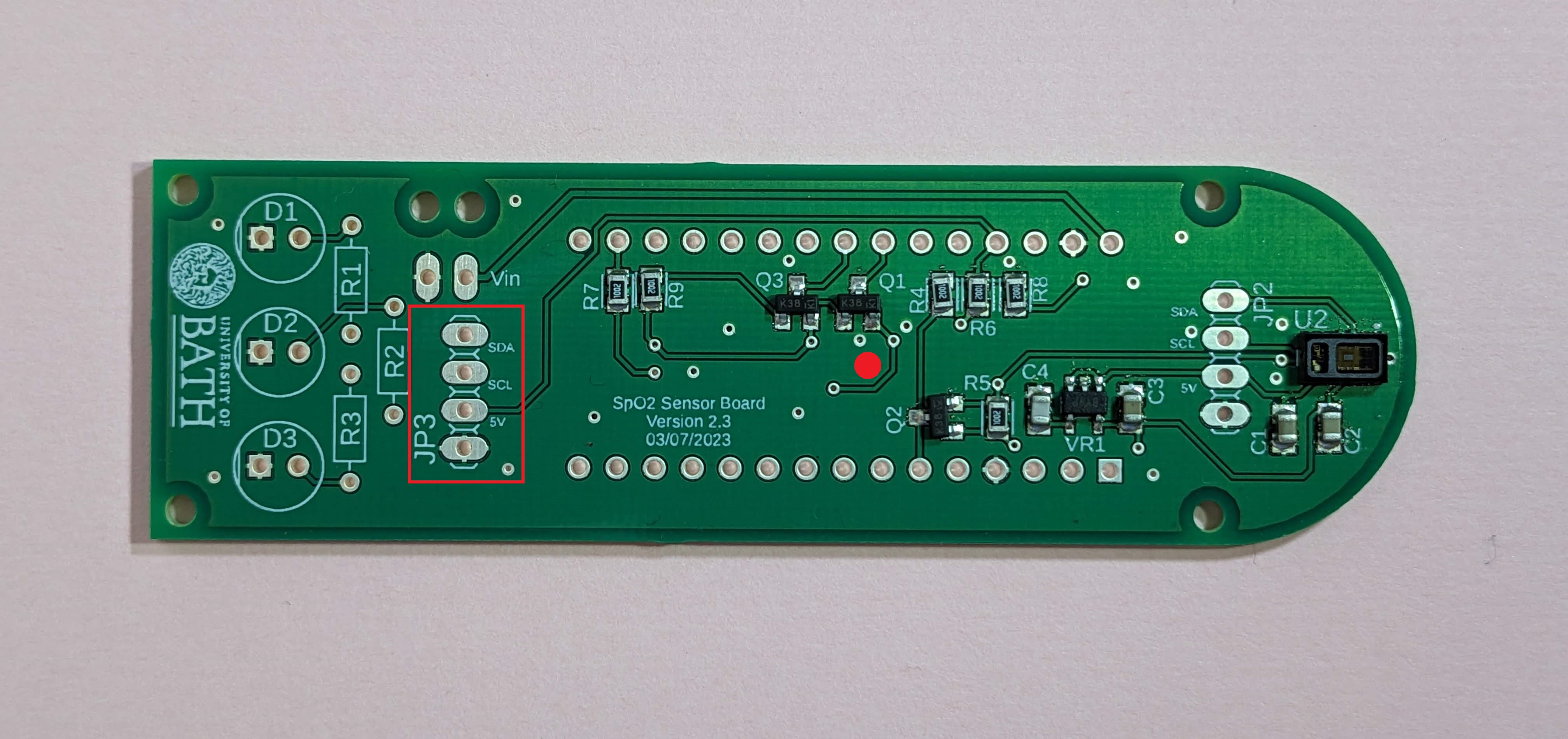
Once you are happy with the screens placement, solder it into place and trim the excess from the screen legs.
Done correctly the board should now look like the one shown in .
The Arduino Nano can be powered using the USB socket or an external power supply. In this case, we will include a battery box on our PCB to power the whole system when we don’t want it connected to a PC.
Adding the Battery
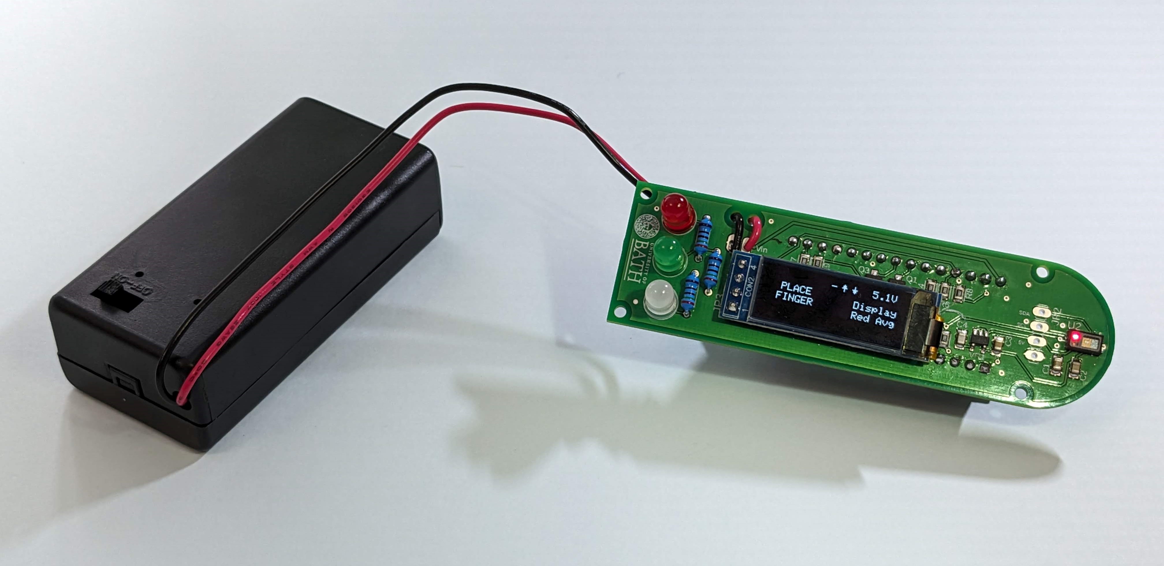
The battery box has two wires, a red wire and a black wire. By convention the red wire represents the positive terminal (+ve voltage), while the black wire represents the negative terminal (-ve voltage or ground). The ends of these wires will be soldered into our PCB, using the two pads left of the VIn designator. However, rather than just soldering them directly into the board, we will first pass them through the holes above the pads. These holes act as stress release, helping to avoid movement of the wires from breaking the solder connection.
Feed the red wire from behind, through the stress-relief hole above the pad labeled VIn (on the right of the two holes) before passing the wire back into the pad below. This will then be attached by soldering the underside of the board.
Do the same with the black wire, feeding it into the second, left-hand hole like before. Once complete, the board should appear as shown in .
Ex. 4 - Designing the Enclosure
Sadly, we won’t be able to use this circuit until we have programmed the board tomorrow. But to complete the design, we will now construct the enclosure.
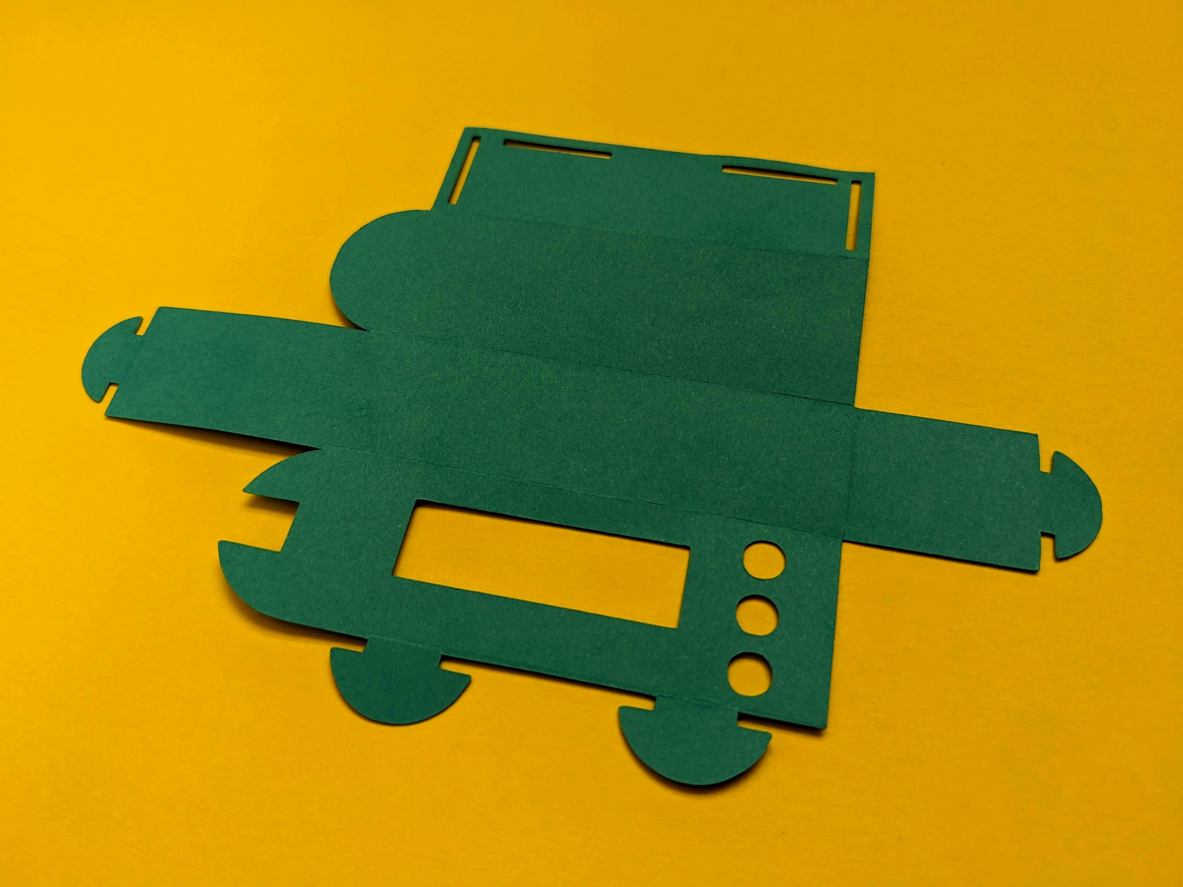
As engineers, it is important to consider the environmental impact of any designs we are involved in building. On this occasion, we have decided to use a simple but responsible material to ensure that we are not adding to the plastic waste issue. As a result the boxes will be constructed from colored card. This gives you a chance to decorate the box yourselves before assembly to truly make it your own.
Designing and assembling the case
Select a color from the available enclosure cutouts and decorate it using pens before folding along the scored lines and feeding the tabs into the relevant holes. Make sure not to glue or fix the flat end of the box as this will need to be opened when programming the system.
Looking ahead
In the next lab, we will introduce you to programming the Arduino Nano. This will involve a set of smaller tasks before we get to adding the code to make the pulse oximeter work.
