EE Summer School - Lab 2
Introduction
The purpose of today’s laboratory is to develop software to control the hardware we previously created. This will be done using a program known as the Arduino IDE (Integrated Development Environment). A set of tasks are provided to help you get familiar with the tool and complete your Pulse Oximeter Board. The final task is left open-ended, allowing you to push your skills and creativity.
What is Arduino?
Arduino is an open-source electronics platform that consists of both hardware and software components. It is designed to be accessible and easy to use for hobbyists, artists, students, and anyone interested in creating interactive electronic projects.
The hardware part of Arduino is based on a microcontroller (or microprocessor) board with various input and output pins that can be connected to a wide range of sensors, actuators, and other electronic components. The microcontroller is essentially the brain of the Arduino, responsible for executing the program instructions and controlling the connected devices.
The Arduino software, also known as the Integrated Development Environment, is used to write, compile, and upload code to the Arduino board. The code is typically written in either the Arduino language, or C/C++, and the files are referred to as “sketches”.
Arduino circuit boards come in different variations, catering to different needs and capabilities. Some have built-in Wi-Fi or Bluetooth connectivity, while others have more digital or analog Input/Output (IO) pins, memory, and processing power.
Arduino is widely popular because of its simplicity, low cost, and extensive community support. It has enabled countless projects and innovations in areas such as home automation, robotics, Internet of Things (IoT), art installations, and many other creative applications. Whether you’re a beginner or an experienced electronics enthusiast, Arduino provides a versatile platform for bringing your ideas to life.
Interfacing with the Arduino
There are two main types of I/O pins on the Arduino boards:
- Digital I/O:
- Pins can have a value of either High (5V) or Low (0V).
- Connect to digital peripherals such as buttons, switches, displays, ect.
- The Digital pins are numbered 0-13 in the Arduino IDE, allowing you to control a specific pin
- Analogue I/O:
- Pins can work with continuous values between (and including) the two power rails, which in this case are 5V and 0V.
- Connect to analogue peripherals such as potentiometers, light sensors, microphones, load cells, ect.
- The Analogue pins are labeled A0, A1, etc. in the Arduino IDE.
Another important way of interacting between the Arduino and other components or systems is serial communication. This allows the arduino to talk to more complex peripherals such as computers, Bluetooth chips, or accelerometers using a pre-defined communications protocol on a small number of I/O pins.
The Arduino IDE and sketch template
Let’s start by looking at the Arduino IDE and the empty “sketch” template where you will ultimately write your code. Depending on the version of the Arduino IDE that you have installed, the window may looking like that shown in either or .
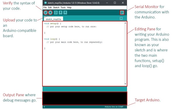
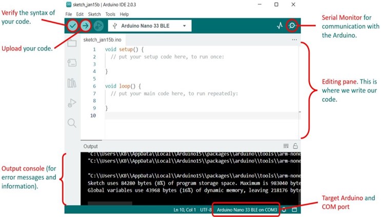
When you open the Arduino IDE for the first time, you should see the code for an empty program with only the setup() and loop() functions defined. This is where you will fill in your code and it is referred to as sketch. A sketch is simply a text file that describes your program in the Arduino language. Each Arduino program is broken into three key parts:
- The declarations are used to create global variables (effectively named containers that are used to store and reference values within our code) or link to external libraries and code that will be used inside the sketch. These are typically located at the top of the file.
- The
setup()function describes anything that the Arduino needs to do once, right at the start of the program. Such as initialise a sensor, or start a serial communication protocol to communicate with a computer or peripheral. - The
loop()function describes the things you want the Arduino to do repeatedly, in a loop, for the rest of the time that the board is powered. Things like measure and record temperature, output a sound on the buzzer or display something on a screen. This is where most of your code will go and can be considered the main program of the Arduino.
Saving your Sketch
Once you start writing code, it is recommended that you save your sketch to a convenient location using the File -> Save As… menu option. The default location to save your sketches is usually “/Documents/Arduino/” and this will suffice for our purposes. Though you may want to locate and email yourself with the files before the end of the summer school, so that you have a copy before leaving.
Debugging and Errors
You can use the verify button in the Arduino IDE (see Fig. 4) to check if you have written your code correctly and the upload button to upload the finished code to your board. If there are errors in your code, the IDE will warn you and stop you from uploading it. You will instead need to work out the cause of the errors and debug your code. Some common causes of errors and bugs are:
- spelling mistakes
- missing semi-colon(s) (;) at the end of code statements
- undefined variables
- incorrect or incomplete use of brackets
Debugging can take time and patience is key.
Errors will be printed at the bottom of your Arduino IDE sketch environment, usual in red or orange text to highlight that there is an issue. Reading this error message will often help shed light onto what is wrong. However the IDE does not always point you to the exact line of the code where the error is located, so you may need to look through the code to locate the error yourself.
Ex. 1 - Blinking an LED
Making an LED blink on the PCB is a really useful way to check that the setup and systems are all working correctly before committing to writing a long and complex program. In this case, we will write a simple program that blinks a light on and off, which will introduce you to the development environment. This will also help check that the connections on the PCB are correct, and the LEDs are functional.
Creating global variables
Variables are named storage elements that can be accessed and changed in the code. A bit like how in the equation $y = mx+c$, the variables $m$ and $c$ may be set to a value to represent a specific line. Variables allow programmers to give meaningful names to data, for reference and use later on. Global variables are special in that they are available for use anywhere in the code, in contrast, local variables are usually more limited for what code can actually access them.
In your empty sketch, before the setup() function, define the name and pin number of whichever LED you will use (in our case, on the SpO2 board, the red LED is connected to pin D9, the green LED to pin D8 and the dual LED to pin D7). Therefore, we can define our LED pin to be digital pin number 7, 8, or 9, for example:
1
2
3
// Define the name and pin number of the LED
const int redLed = 9;
You can create variables for each LED if you’d like (sadly, due to an electrical error we just spotted on the board, the Dual LED will only light up one color).
Configuring the Pin Direction
As the name would suggest, the digital I/O pins can act as either input or output. We need to make sure that we tell our code which way the pin will be working before we try to do anything with it. Otherwise we could end up trying to change the value on a pin that is being set externally.
In the setup() function (the part of the code that only runs once as the board boots up) we need to declare whether each pin should be an Input or an Output. In this case, we are going to drive the LED, which means our pin should be defined as an Output (this is measured relative to the Arduino, so output signals flow out of the Arduino).
We can do this using a special function called pinMode(), as follows:
...4
5
6
7
8
9
10
void setup() {
// Configure LED pins to be output
pinMode(redLed, OUTPUT);
// Make LED start off (set it to LOW)
digitalWrite(redLed, LOW);
}
In this case, the OUTPUT (and conversely INPUT) are keywords that this function takes as an argument to tell it how to set up the pins. This special pinMode() function is fully described in the Arduino documentation
You will notice that the code above also turns off the LED by setting it’s value to LOW. This is generally good practice as it avoids any errant signals moving around the PCB while the board boots up.
If we programmed the board with the code we have now, nothing would happen. This isn’t a bug, we have simply only configured the pins so far, and not actually told the LED to turn on at any point.
Making the LED Flash
In order to ensure that the LED flashes continuously, we need to add the next code into the loop() function. Remember, this function will run through the code we write in it repeatably, in a loop, forever. Since we want to blink the LED, we also need to decide when it should turn on and off and for how long it should stay in each state. Like before, we can set the state of the pin using a function called digitalWrite() which either turns the LED ON by outputting a HIGH voltage to our LED pin (i.e. 5V or a 1 state) or a LOW voltage (i.e. 0V or 0 state).
We also need to make sure that the LED stays on/off for a small amount of time in each state before moving onto the next state. Otherwise the LED will flash so fast that our slow human eyes won’t see it changing at all! This can be achieved using the delay() function which may be found in the Documentation. This function takes a number in milliseconds (e.g. 250) as an argument and waits that long before progressing.
With this information, try to write some code that turns the LED on, waits for 250ms, turns the LED off and waits for another 250ms. If this happens in a loop, you should find that the LED will flash.
Programming the Arduino
If you haven’t done so already, connect your Arduino to the computer using the USB cable provided. Then click the Verify button and check for any errors in the console at the bottom. If errors are reported, see if you can work out what they might mean, but feel free to grab a demonstrator to ask for some help.
Once all errors have been dealt with, and the Verify operation is error free, you are now ready to upload your code onto the board. Click the Upload button and wait for the board to be programmed.
If you see the LED blinking, then congratulations! You have just written a fully functional Arduino program or sketch. If not, then there is either an issue with the code or the LED, you could try changing which LED should be flashing by changing the Pin number in your code to see if that is the issue.
Making the LEDs Ripple Challenge
Now that you have managed to get one LED to flash, see if you can get the LEDs to cycle in order (Red -> Green -> Clear) using the information you have seen so far. What would be required to make the system flash the Red LED three times before starting this cycle?
Ex. 2 - Serial Communications
So far, we have used the digital and analogue I/O pins to interface between our microcontroller and simple devices (like LEDs) but how do we interact with more complex devices, such as the computer or the pulse oximeter sensor? One of the simplest methods is by serial communication. Serial communication is a method of transferring data between two devices or systems one bit (or High/Low voltage pulse) at a time over a single communication line. Serial communication uses a wire or data line to transmit and receive the data, and often includes a clock line, which is simply a toggling signal to synchronize the two systems.
In serial communication, data is transmitted in a sequential fashion, bit by bit. This typically uses specific protocols and timings to ensure accurate and reliable data transfer. The two main devices involved in serial communication are the:
- Transmitter: The device that sends data, converting it into a serial stream (a series of 1’s and 0’s) and transmitting it over the communication line.
- Receiver: The device that receives the serial data stream, converts it back into meaningful information, and processes or displays the data.
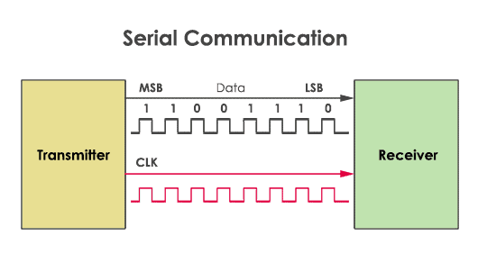
Arduino comes with a useful set of functions called Serial that are built in to make serial communications easier to implement. To use these functions we must first create a serial connection using Serial.begin(9600). The value 9600 is called the baud rate of the connection, and defines how fast the data is sent over the line.
When using an Arduino device you will often encounter a similar begin() function to initialise different peripherals and communication protocols.
After starting the communications protocol, you can freely use functions from the Serial library, such as:
Serial.print(): which sends the text in the parentheses along the serial line (usually to the computer along the USB).Serial.println(): which does the same as above, but also starts a new line by sending a new line character to terminate the message.
Use the code below to create a new sketch and upload it to the Arduino.
1
2
3
4
5
6
7
8
void setup() {
  // Create the serial interface and set the baud rate
  Serial.begin(9600);
  // Send the message "Hello, World!" along the serial line.
  Serial.println("Hello, World!");
}

void loop() {}
Now, in the Arduino IDE, open the serial monitor using Tools -> Serial Monitor. This will open a new window, showing the message that was sent by the board. If you push the button on top of the arduino (which is the reboot button) you should see that the message is sent again as the board starts up.
Try sending different messages using both, Serial.print() and Serial.println(), to get a feeling for how they both work.
Ex. 3 - Device Libraries
s well as the numerous tutorials, guides, and community forums to help users troubleshoot issues and find inspiration for their projects, one of the best things about Arduino is it’s a vast library ecosystem, offering pre-written code to simplify complex tasks. These libraries are a key element that empower users to create diverse and innovative projects with minimal effort. They play a crucial role in making Arduino accessible to a wide audience and encouraging rapid creativity in the world of electronics and programming.
The OLED Screen
The screen being used for the Pulse oximeter is a monochrome 128 x 32 pixel graphic OLED display which uses the SSD1306 chip. Both the screen assembly and the chip itself have their own datasheet, available at:
We will use a pre-made library for the SSD1306 for the first part of this lab.
Installing the SSD1306 library
Install the new library by going to Tools -> Manage Libraries… to open the library manager. Then search for ‘Adafruit SSD1306’ and select Install -> Install all (for any missing dependencies). This will install the code required to drive the screen, saving you from needing to read and digest the full screen datasheet.
Now that we have installed the library, we actually need to tell our code to use it. Otherwise it will be left out of our compiled solution to save space.
We will actually use two libraries here, one that was already installed called Wire and the one we just installed called Adafruit_SSD1306.
The Wire library is a lot like the Serial command, but it allows us to implement something known as the I2C protocol for communications.
Start a brand new sketch/project and add the following code:
1
2
3
4
5
6
7
8
9
10
11
12
13
14
15
16
17
18
19
20
21
22
23
24
25
26
27
28
29
30
31
32
33
34
35
36
37
38
39
40
41
// Link to the required libraries for the OLED screen
#include "Wire.h"
#include "Adafruit_SSD1306.h"

// Define the screen dimensions and initialize setup display functions
#define SCREEN_WIDTH 128
#define SCREEN_HEIGHT 32

Adafruit_SSD1306 display(SCREEN_WIDTH, SCREEN_HEIGHT, &Wire, -1);

void setup() {
  // Attempt to initialize the display with the I2C address of the OLED (usually 0x3C)
  if (!display.begin(SSD1306_SWITCHCAPVCC, 0x3C)) {
    Serial.println(F("SSD1306 allocation failed"));
    // Pause the program
    for (;;);
  }

  // Clear the display buffer (it's internal memory)
  display.clearDisplay();

  // Set the screen text size
  display.setTextSize(1);

  // Set text color to white
  display.setTextColor(SSD1306_WHITE);

  // Print a message on the display, Feel free to try other messages.
  // Note F() is required to format the text in memory correctly
  display.setCursor(0, 0);
  display.println(F("Hello, OLED!"));
  display.println(F("Welcome to Arduino"));

  // Refresh and update the display
  // The display requires refreshing every time you want to show a new frame
  display.display();
}

void loop() {
  // Nothing to do here
}
Run this code on the arduino and read through the code to try and understand what it is doing. Feel free to adjust the messages displayed on the screen or play around with the cursor position to understand what it is doing.
You will notice that we had to use the display.clearDisplay() and display.display() functions. These are key in using the screen.
The clearDisplay() function empties the screen, to make it ready for a new image. We then prepare the frame by combining commands to add text or images as needed.
The new frame is then displayed by calling display() function.
Once you are familiar with the previous example, let’s look at one of the examples provided with the library that show what is possible.
Select File -> Examples -> Examples from Custom Libraries -> Adafruit SSD1306 -> ssd1306_128_32_i2c.
Look through the code and see if you can work out what it will do and then upload this sketch to your Arduino to see if you were correct.
The full list of commands that may be used to modify each frame are detailed in the library documentation.
Pulse Oximeter Sensor (MAX30101)
As before, we can save some time by installing a custom library to allow us to easily interface with the pulse oximeter sensor chip.
Install the SpO2 sensor library by first opening the library manager like before and then searching for ‘MAX3010x’. Select ‘SparkFun MAX3010x Pulse and Proximity Sensor Library’ and install it.
Got to File -> Examples -> Sparkfun MAX3010… and open example 8. Have a scroll through this and then upload it onto your Arduino. As you upload, take note of the amount of memory that the IDE reports using - why do you think this might be an issue?
Open the serial monitor again once the upload has finished and follow the instructions on screen to test if you can get a pulse reading.
Ex. 4 - Bringing it all together
We have now seen how an engineer might test and get familiar with the various parts that make up the pulse oximeter solution. But to truly produce a finished project we need to bring these concepts together and make them work exactly how we want.
Unfortunately, this is not always so easy to do. Indeed, we have already seen that some of the libraries we downloaded take up a considerable amount of free space in the memory of the Arduino Nano. As a result, some of the code would need to be optimised, and maybe even re-written, to ensure that the code all fits in the chips memory.
This would not be an easy task - but luckily you don’t have to start from scratch! This project was originally part of an initiative to build an open-source pulse oximeter called OpenOximeter, and there is, therefore, a functional solution already available online.
Downloading and Opening the Code Project
Navigate to the OpenOximeter Arduino Code Repository and download the source code as a Zip file using the download button shown in .
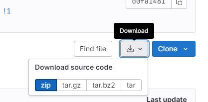
Save this zip file somewhere and then go and unzip it. This will create a new folder than contains a file called PPG_Generic.ino inside a PPG_Generic folder. Switch to the Arduino IDE and open that file using File -> Open.
When you open this project, it will open multiple tabs. Each tab is it’s own separate file and represents a small part of the overall solution. The code is broken up in this way to make it easier to edit and maintain. Looking at the folder again, you may notice that some of the files have a .cpp extension. These are actually files that have been coded in C++ instead of the Arduino’s language. This was done because C++ is much faster and more efficient when running on the hardware.
Every C++ file also comes with a .h file, which define key values for that part of the code and also tell the compiler what functions and classes exist inside the associated C++ file.
These files are quite complicated in places, but for those who are interested they can be somewhat described as follows:
-
Beat: A class that performs filtering and analysis on pulse signals to identify if a heart beat was present in the raw data. This filtering is required because the sensor often has lots of noise (or errors) in the values that it detects.
-
MAX3010x: An alternative SpO2 library written for the MAX3010x chip family (the pulse oximeter sensor on your PCB). This library has been stripped down to the bare requirements to ensure that there was sufficient memory on the Arduino Nano for other functions. The functions that this optimized library supports can be found listed at the bottom of the ‘MAX3010x.h’ file, shown below. These should be comparable to some of the key functions we saw in example 8 of the pulse oximeter library we previously downloaded.
...146
147
148
149
150
151
152
153
154
155
156
157
158
159
160
161
162
163
164
165
166
167
168
class MAX3010x{
public:
MAX3010x(void);
boolean begin(uint8_t i2caddr = MAX3010x_ADDRESS);
// Setup the IC with
// powerLevel = 0x1F, sampleAverage = 4, Mode = Red and IR,
// sampleRate = 100, pulseWidth = 411, adcRange = 4096
void setup();
void off() {writeRegister8(REG_MODE_CONFIG,0x80);}
//FIFO Reading
uint16_t check(void); //Checks for new data and fills FIFO
uint8_t available(void); //returns number of samples available (head - tail)
void nextSample(void);//Advances the tail of the sense array
uint32_t getRed(void); //Returns the FIFO sample pointed to by tail
uint32_t getIR(void); //Returns the FIFO sample pointed to by tail
// Low-level I2C communication
uint8_t readRegister8(uint8_t reg);
uint32_t readFIFOSample(void);
void writeRegister8(uint8_t reg, uint8_t value);
-
RollingAverageByte: Rolling average filters can be a really good way to extract a trend from live data. The only issue is that such filters typically require large chunks of memory to store the previous $n$ values seen, where %n% is the number of points in your rolling average. The higher the value of $n$, the better the filter is at extracting slow changes in the data, but the larger the memory load. As memory is tight on this project, this filter was not used in the end (you can see the include for this file commented out on line 2 of ‘Beat.h’).
An approximation of this filter was actually built into Beat.cpp, called the MAFilter, which manages to closely approximate this rolling average filter without requiring the large memory usage. This approximation is achieved by use of some cheeky maths techniques, resulting in a small loss of accuracy in the result in exchange for a massive saving in the memory requirements. -
font.h: The only ‘.h’ file without an associated ‘.cpp’ file. This file contains the letters encoded as raw bits that are used when writing to the display. You can think of this like a font file in word, that tells the computer which pixels should be on for any given letter. Scrolling down this list you may notice that there are some additional characters defined at the end which were going to be used in the final solution. These include an approximation symbol (~) to be used when the value was still uncertain (i.e. while the filter was still collecting data just after the system is powered on) and an up and down arrow to show if there was any trend in the data being plotted. These features were never actually implemented in the code due to time constraints, but the arrows do shown on screen when no finger is present on the sensor.
-
ssd1306h: A stripped down and optimized version of the SSD1306 library we saw previously. This library has had a number of the draw functions removed, but also includes a new
invertDisplay()function that is called whenever the blood oxygen level is concerningly low. You will likely see this in effect when you get round to running the code, as the reading levels take a few seconds to settle each time you place your finger on the sensor.
The PPG_Generic file is the main file, where the setup() (line 217) and loop() (line 241) functions that we have grown accustomed to may be found.
We are largely going to leave the C++ files alone, however there is one small edit that we must make to ensure that this code works on our boards…
Configuring the Code for Your Hardware
This code was designed to work with a range of pulse sensors, so we need to tell it specifically which sensor we have fitted to our board.
In your case, the sensor is a MAX30101 chip. Open the MAX3010x.h file change line 3 to read:
...3
#define MAX30101
This will tell the code to configure the Arduino to talk to the chip in the correct way, ensuring that we get meaningful results.
Save the file, and then switch to the PPG_Generic tab and program your Arduino using the upload button. If successful you should see the OpenOximeter message appear on your screen once the programming finishes.
Make sure that the board seems to be working correctly by placing your finger on the pulse oximeter sensor and waiting for about 10 seconds to see if the values settle to meaningful numbers. A resting heart rate is typically between ~60 bpm and 100 bpm, while oxygen level would typically be between 95% and 100%.
Challenges and Ideas
You now know how to download and install the default OpenOximeter code onto your board. This means that you are free to try and make edits to the code and see if you can ‘improve’ the design in some ways.
This is intended as something of an open exercise, so feel free to experiment, however below are some suggestions of things you could try. Note that some of these are very challenging (I say that even as the original author of the OpenOximeter code), so don’t feel discouraged if you can’t get them to work. I have tried to order the suggestions in order of increasing difficulty (though this is just my own personal prediction of difficulty).
- Edit the boot message to say something that is more personal for you.
- Make one of the LEDs on your custom PCB flash every time a heart beat is detected.
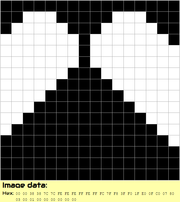
- Edit the heart icon (this is less easy, as the heart is coded as a inverted and shifted binary image called heart_bits in PPG_Generic - see lines 33-37). There is an online tool that can help create the Hex values, however you must bear in mind that the image is inverted and shifted right by ~50% of it’s width. A demo of the current boot logo, as recorded in the code, may be seen in . See if you can spot the relationship between the image hex values and the data provided in the code.
- Make an LED that tells the user when the reading values have settled (i.e. when approximately 10 display refreshes have happened since the finger was first detected). This will require you to create a global variable to count the number of refreshes seen, then identify where the code checks if a users finger is present. If no finger is present, the refresh count must be set to zero, but if a finger is on the sensor, the the refresh count should be increase by 1 whenever the display is refreshed (in this case it is called
draw_oled()). Some code at the bottom of the loop should then check the refresh count, and set the LED high if it is greater than 10.
Wrap-Up
We hope that you have enjoyed exploring this electronics project with us. If you have any feedback then please don’t hesitate to let us know or tell your summer school guides. The Arduino and PCB are yours to keep and play with at home - but please return the see-through storage box that the components originally came in so that we can use it again for the next summer school.
On the next page there are some further details about how you could use the Arduino at home, as well as more information and links regarding the undergraduate courses offered here at Bath.