Modular Display Project - PCB Schematic
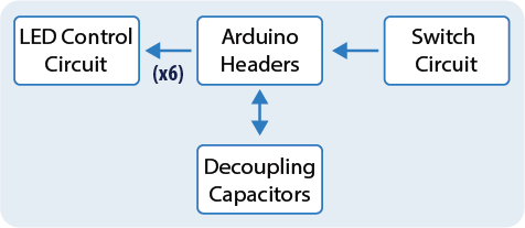
The PCB will contain 4 key elements, shown and described in the figure and table below, respectively. This lab script will guide you through the design of the PCB schematic to include those elements.
| Element | Function |
|---|---|
| Arduino Headers | Arduino headers allow the PCB to connect to the Arduino without the need for direct soldering, facilitating easy integration and modularity. |
| LED Control Circuit(s) | Provides power to LEDs and controls their on/off state using signals from the Arduino. It ensures the correct voltage and current is supplied to each LED for optimal operation. |
| Switch Circuit | Enables manual system control through a mechanical switch. |
| Decoupling Capacitors | These capacitors filter out high-frequency noise from the power supply, stabilizing voltage and preventing disruptions to ICs. They act as small localised power sources/reservoirs during brief voltage dips, ensuring smooth operation. |
ORCAD Setup
Before beginning the design process, it is essential to first add the required libraries to OrCAD capture. These libraries were obtained directly from the manufacturers of the components to be soldered onto the PCB and include some of the more bespoke elements, such as the high-power LEDs and switch. This step ensures that all symbols and footprints are correct when performing the PCB layout and manufacture later down the line.
Components such as resistors and capacitors will not require a special library as they are standard parts. They will, however, require that you ensure the footprint is correct when using them. The libraries, part names and footprints may be found in the table below.
| Component | File | Library | Part name | Footprint |
|---|---|---|---|---|
| Capacitor | N/A | ANALOG | C | SMC1206 |
| Resistor | N/A | ANALOG | R | SMR0805 |
| LED | WL-SMTW_rev23a | WL-SMTW | SMTW_3528_150141YS73140 | WL-SMTW_3528_PLCC4 |
| Arduino | ARDUINO_NANO | ARDUINO_NANO | ARDUINO_NANO | SHIELD_ARDUINO_NANO |
| BSS123 | ul_BSS123-215 | ORCADCAPTUREOLB | BSS123,215 | sot23_bss123_nex |
| Tactile switch | WS-TATU_rev19a | WS-TATU | 6x6_Right_Angled_ground | ws-tatu_right_angle_ground_terminal_6x6_3r15 |
Setup Exercise: Add the Required OrCAD Libraries
- Start by downloading the .zip file using the download button below.
- Extract the folder and move it to your H drive, placing the contents somewhere sensible.
- In OrCAD, click on
Place Partto view the existing libraries. - If ANALOG is not in the list, add it following the instructions in P2.01
- Following the same process as before, add the rest of the libraries listed in the table above by finding the
OLBfiles in the folders you saved in step 2.
1) LED Control Circuit
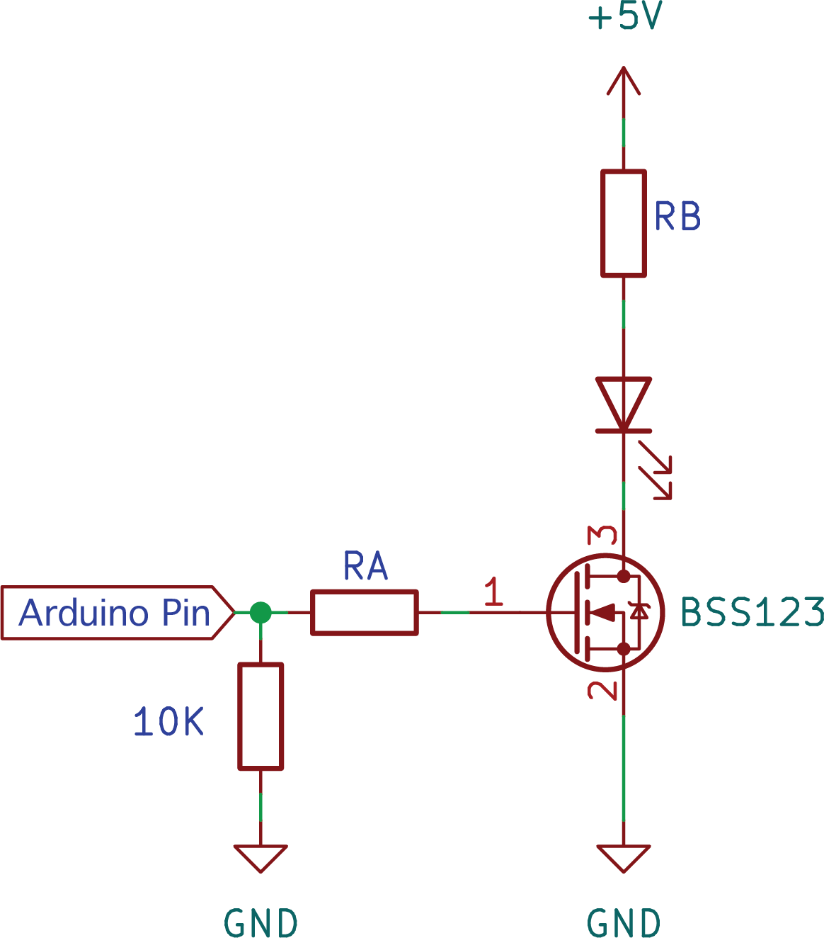
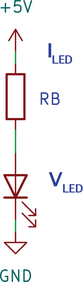
Each Symbol requires a dedicated LED to illuminate it. This LED must be controlled using an arduino, however the current and voltage requirements of the LED mean that this would not be possible directly. An LED Control Circuit is therefore needed, as shown below.
It is modular and allows different LED colours to be used by simply adjusting the resistance RB to ensure that the correct current is provided.
Why is the MOSFET Needed?
The GPIOs (Analogue and Digital pins) on the Arduino Nano ESP32 can source (i.e. provide) currents up to 40 mA, and sink (i.e. receive) currents up to 28 mA. These current limitations fall below the required currents for high-brightness LEDs, and mean that the LEDs used in this project cannot be powered directly through the arduino.
BSS123 is a commonly used N-channel enhancement mode MOSFET (a type of field-effect transistor). This device safely manages the higher currents required by the LED, without risking damage to the Arduino.
In this circuit, the MOSFET acts as a switch. Applying a voltage that exceeds the threshold to terminal 1, known as the gate, allows current to flow between terminals 2 and 3, known as the source and the drain. The beauty of such a device is that the gate is isolated from the source/drain, meaning that the higher currents required by the LED cannot negatively affect the arduino in any way. This allows the lower-current arduino device to control a much larger system.
Why is the 10K Resistor Needed?
The 10K resistor is operating as an external pull down resistor. This ensures that the gate of the MOSFET defaults to ground (i.e. is pulled down) when no voltage is provided by the arduino. Technically, the arduino has software configurable pull-up and pull-down resistors, however this external resistor helps ensure that the LEDs do not flash when the system is rebooted or programmed.
Exercise 1.1: Calculate RA
To safely interface the Arduino’s GPIO with the gate of the MOSFET, a resistor should be placed between them (shown as RA in ). This resistor limits the inrush current to the gate when the MOSFET is switched on, protecting the arduino from excessive current draw and ensuring stable operation.
The circuit below is an approximation of the setup, showing the BSS123 gate as a capacitor (as this is effectively what the gate looks like to the arduino). When first switched on, current will rush into the capacitor (or MOSFET gate), increasing the voltage. In the very first moment after switch-on, this current will flow as if there was a short circuit across the capacitor (i.e. as if it wasn’t there). It is this instantaneous inrush current that we would like to limit using resistor RA.
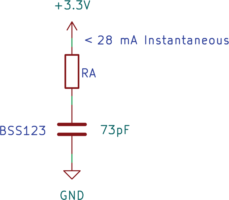
Knowing that the Arduino GPIOs supply a voltage of 3.3V for logic-high signals, and that the current should not exceed 28 mA (both taken from the arduino datasheet), calculate a suitable value for resistor RA.
Available LEDs
The table below shows the different colour LEDs available for you to pick from. Note that they have varying current and voltage ratings. The part number column can be used to look up the part through the supplier website should you so desire: Farnell
| Colour | part # | Vf (V) | I (mA) |
|---|---|---|---|
| Yellow | 3619650 | 2.4 | 50 |
| Red | 3619649 | 2.4 | 50 |
| Blue | 3619646 | 3.2 | 50 |
| Green | 3619644 | 3.2 | 50 |
| White | 1649009 | 3.6 | 30 |
Exercise 1.2: LED Resistor Sizing
When the Arduino pin controlling the circuit is high, the MOSFET allows current to pass between the source and drain. Use the equivalent circuit shown below to calculate suitable values for RB for each LED colour.
Exercise 1.3: Add the LED circuit to the Schematic
Now that you have all the required values, add the LED circuit into your OrCAD capture project. Make sure to go into each component and set the footprint according to the table in the ORCAD Setup section above (you can double-click on the components to see their properties). Once you are done and you are sure all the components have the right footprints, create 5 additional copies of the LED circuit, one for each of the six sheets in the display.
Below are some useful tips:
- You may wish to use the
Place Portfeature to add the connections to the Arduino pins rather than drawing wires everywhere. - You may find it useful to rename the Arduino ports to a more useful name. For example, Symbol n, where n corresponds to the sheet number, from 1 to 6.
- You can use
VCC_BARwithin Place -> Power to add the +5 V, which will later be linked to the correct arduino pin. - If your schematic page size is not large enough, you can increase it by going to Options -> Schematic Page Properties.
- The LED has 4 connections instead of the usual 2. Looking at the datasheet for the part will explain where each connection goes.
2) Switch Circuit
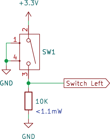
The tactile switch provides additional functionality to the modular display, allowing it to respond to user input. Below is a schematic of the switch circuit which includes the switch and pull down resistor. The ‘Switch Left’ port should be connected to the arduino.
Exercise 2.1: Add the switch circuit to the Schematic
Use the schematic shown above to add the switch circuit to the PCB schematic. The symbol may appear differently to that of the one in the image - ensure that you connect the pins on the outer case to ground.
3) Arduino Headers
The modular display is managed by the Arduino, so it’s necessary to interface the Arduino with the wider schematic. This is done via the arduino header and ensures that the LED control circuits (all six of them) and the switch circuit can be properly connected and work together as intended.
Exercise 3.1: Add the arduino pins
Follow the steps below to connect the circuits to the arduino:
- Add the arduino part from the ARDUINO_NANO library
- Place power and ground according to the arduino pins.
- Use digital pins 1 to 6 to control the 6 LED circuits.
- Connect the switch output to digital pin 7.
4) Decoupling Capacitors
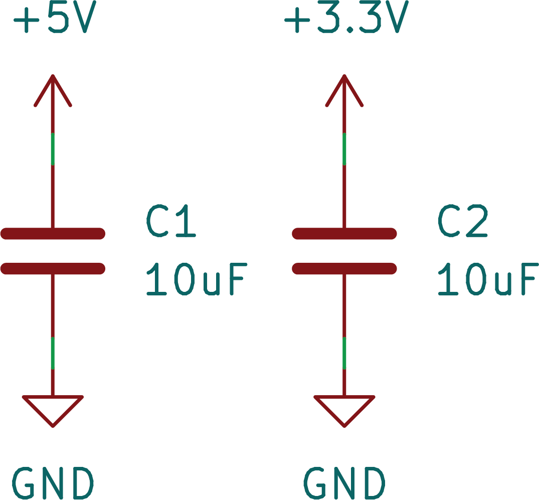
Decoupling Capacitors are used to smooth out voltage fluctuations on the power supply lines that can occur due to sudden changes in load (like when a microcontroller or other components suddenly draw more current). They are placed as close as possible to the power supply pins of integrated circuits (ICs) or other sensitive components to help maintain a steady voltage level, reduce noise, and improve the overall stability of the system.
Exercise 4.1: Add decoupling capacitors
Follow the schematic below to add decoupling capacitors to the two voltage rails of the arduino.