Modifying a simple part with CAD
Introduction
Last week we designed a simple Arduino enclosure using Autodesk Inventor. The aim of today’s lab is to mimic the design process where you have to make modifications to your design after producing the fist prototype.
The first prototype
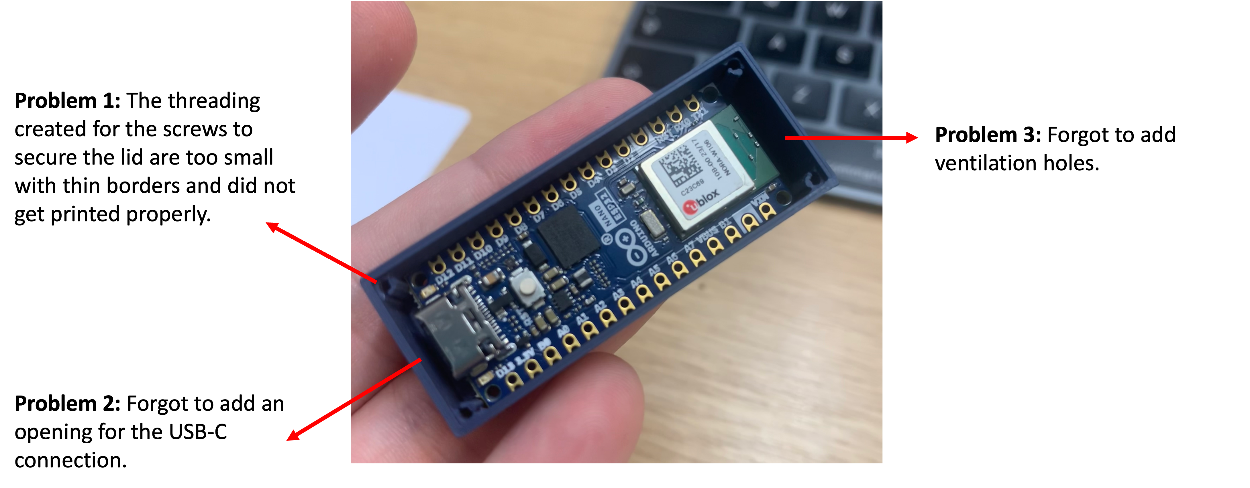
Imagine this situation: Having 3D printed your design, you notice a few issues and you decide to make some modifications accordingly. Below is an image of the prototype with comments identifying the problems that need to be resolved.
The Arduino
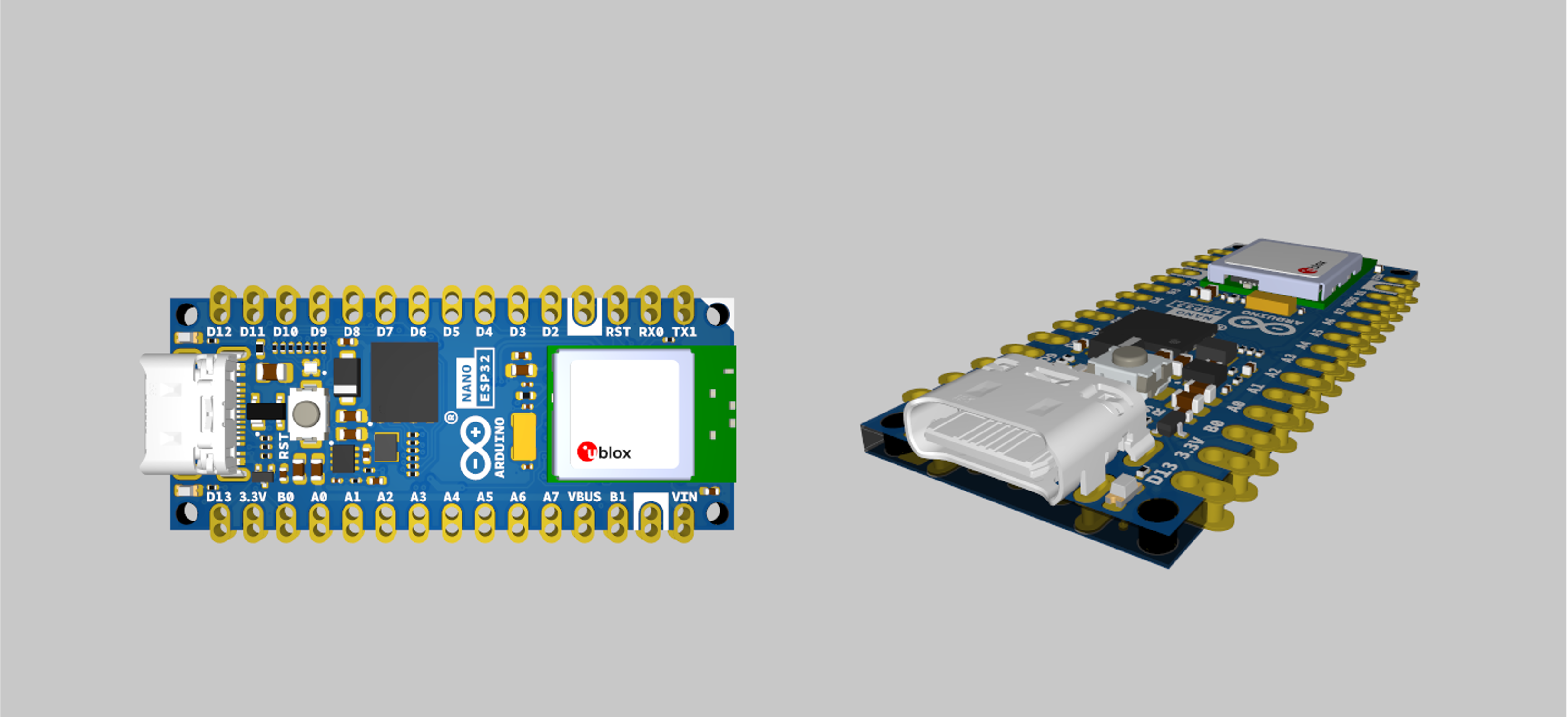
As a reminder, the part we are designing is a very basic enclosure for an Arduino Nano ESP32, which is the microcontroller you will be using throughout the year. (You can read more about it here)
The Arduino Nano ESP32 features the NORA-W106, a module with a ESP32-S3 chip inside. This module supports both Wi-Fi® and Bluetooth® (5.0 and above), making it an ideal device for IoT development. The popular Nano form factor also makes it compatible with many hardware accessories.
Arduino Nano ESP32 is the first Nano board to feature a USB-C® connector!
The mounting dimensions of the arduino are shown below.
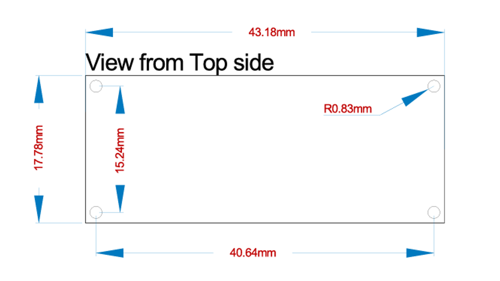
You can use the Measure tool with the CAD model of the arduino (downloadable using the button below) to measure any other dimensions you may need.
Understanding the changes that need to be made to address the issues
Before starting to modify the features, lets go through the issues and identify how we can address them.
Problem 1: Threading to fasten the lid
- The current threading is M1.6, M3 would be more suitable which would require the dimensions of the extruded square to be increased by at least 1.5 cm.
- The walls were too thin so the dimensions of the extruded square to be increased by an additional 1.5 cm.
- This makes the overall dimensions of the extruded squares
5 cm x 5 cm. - In order for the Arduino to still fit within the enclosure, the wall will need to be pushed back by
6 mmin each axis.
Problem 2: USB-C Connection
The first step is to identify the size and location of the USB-C connector using the measure feature.
Exercise
Search online for the dimensions of a USB-C cable and use that to calculate the required dimensions of the opening for the USB-C connection. You may find sketching it on a paper to be useful.
Problem 3: Ventilation holes
Designing ventilation for electronic component enclosures is essential to prevent overheating adn ensure proper airflow. This can sometimes include a rigorous process of calculating heat dissipation and, where appropriate, modelling the heat flow within the enclosure. However, the arduino is not expected to dissipate a worrying amount of heat so simple vents should be sufficient.
The part of the arduino which is expected to dissipate the most heat is expected to be the microcontroller itself (ublox chip).
Modifying the box dimensions
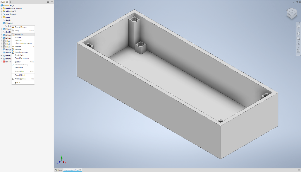
The model browser allows us to edit features and sketches we used before to modify the design without having to start over.
- Find the first extrusion you created, press the
+button to show the sketch used to create it, right click on it and press onEdit Sketch.
- You will now be able to change the dimensions of the outer and inner rectangles in the sketch as follows:
| Box | Old Value | New Value |
|---|---|---|
| Outer | 50 mm | y=56mm |
| 20 mm | x=26mm | |
| Inner | 48 mm | y2=y-2 |
| 18 mm | x2=x-2 |
- Note that we did not simply change the value, instead we are using parametric CAD where you can define variables to help with automating parts of the CAD process.
- Now, if you need to change the box dimensions, you will be able to change x and y, and y2 and y2 will change automatically to keep the wall thickness of 1 mm.
- Press
Finish Sketch.
Examining the results
- If you have followed the lab script from last week, the resulting part should look like the one below.
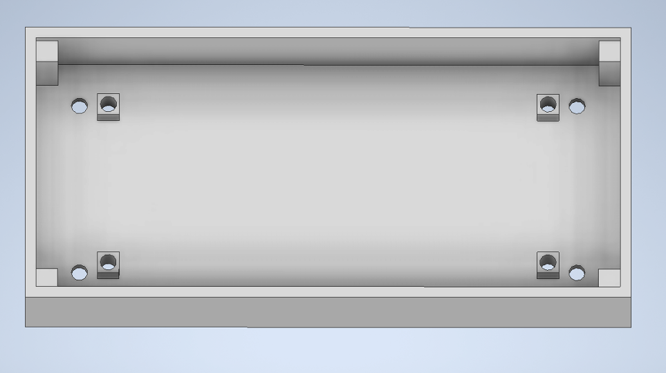
- Note that the extruded outer squares moved out with the box. That is because we aligned one corner with the corner of the box.
- Note, however, that the threading did not move correctly. That is because we placed them in the centre of the box visually without proper alignment.
- The pillars and threadings used to secure the arduino in place will not need modification for now.
- Note that the mirroring option meant that the 4 sides of the box look the same even after modification.
Modifying the Extrusions and Threading
- Similar to the previous step, locate and access the sketch used to create the pillars where the threading was added.
- Change the dimensions of the outermost square (Square A) to
5 x 5. - Before we edit where the hole is places, we can use
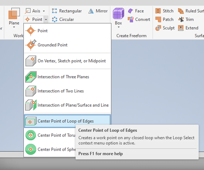
Work Featuresto help us locate it correctly. - Within the banner, locate the
Work Features->Point->Centre Point of Loop of Edges. This point will be a reference that identifies the centre of the face.
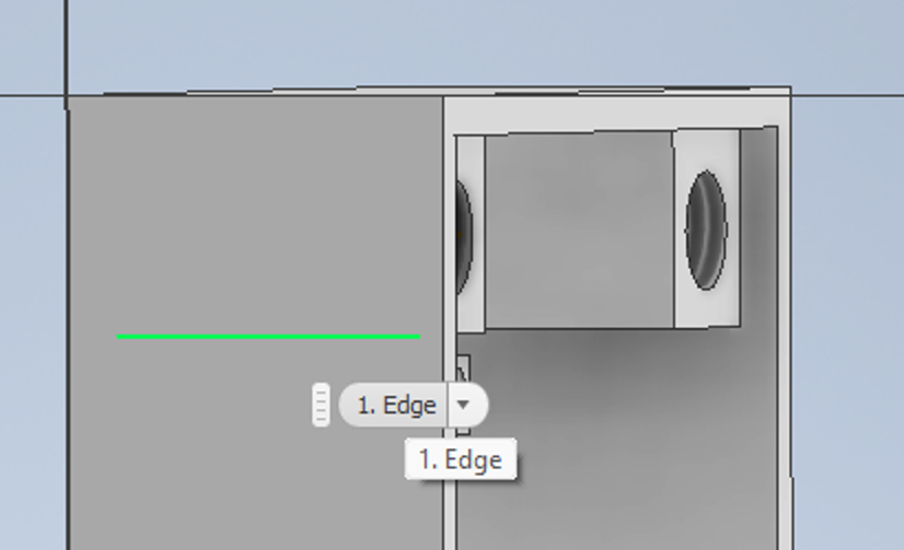
- Right click on
Hole 1and clickEdit Feature. - In the new window the pops up, click on the x next to 1 Position to get rid of the original hole.
- Hover over the cross in the centre (which is the point we added earlier) and click on it when it turns green.
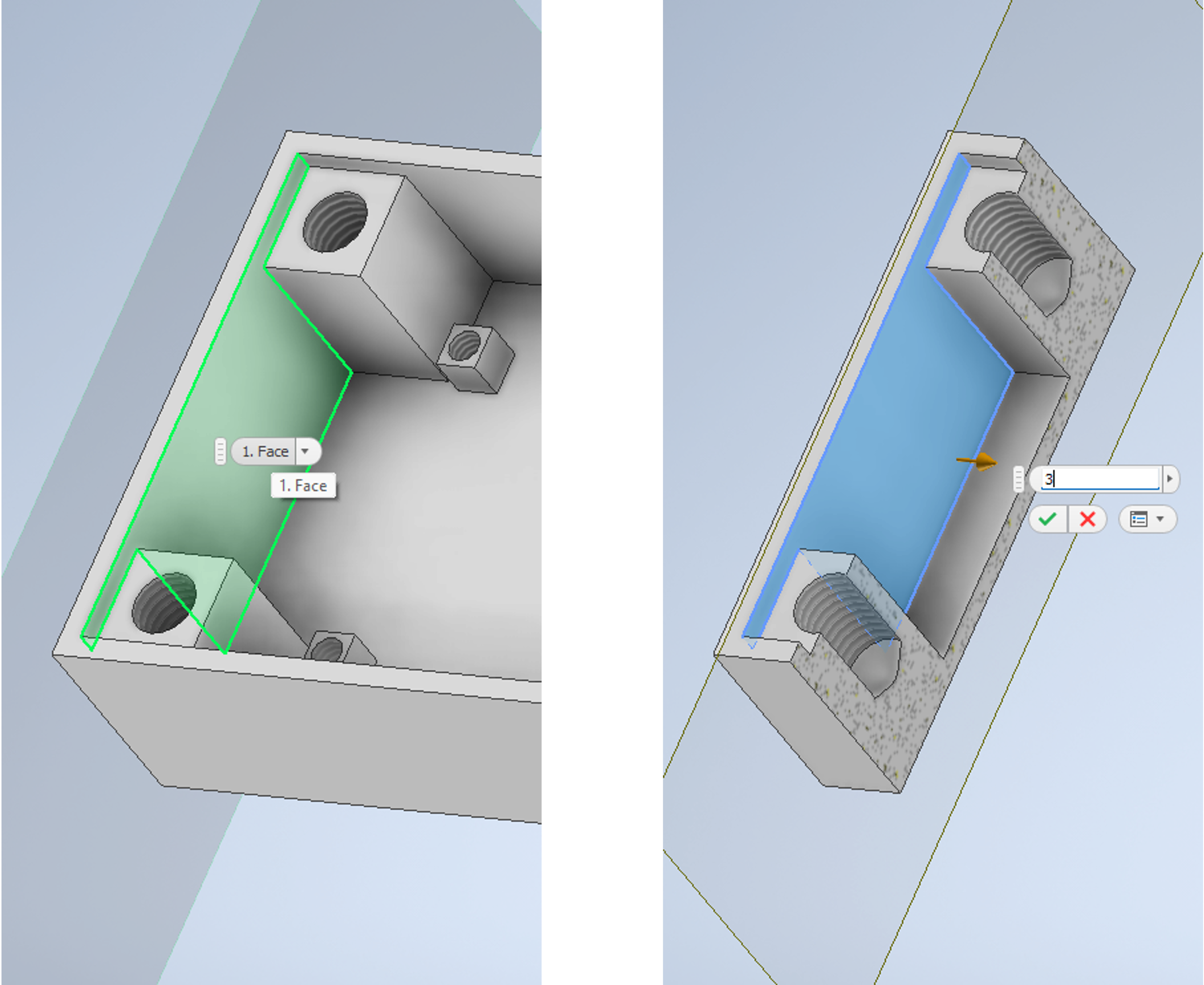
- Change the hole dimension from 1.5 mm to
3 mm. - We do not need the threading to be all the way through so change the
TerminationtoDistance, and set that to5mm. - Similar to the steps followed above, change the feature
Thread 1to be M3.
Adding Air Vents
- Create a sketch on the long side of the box.
- Use the
Project Geometrybutton to mark where the pillars end, as shown below.
- Sketch a
1 mm x 8 mmrectangle1 mmaway from the projected line. - Extrude the square rectangle by
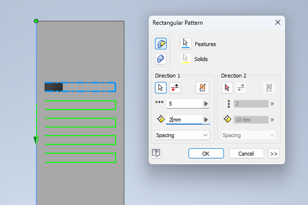
1 mminto the box, making sure you are using theCutoption. - Click on the extrusion you just created then locate the
Patterntab in the top banner and selectRectangular. - Create a pattern of 5 vents that are 1 mm apart (spacing= 2mm), by using the settings shown below.
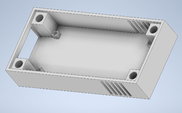
- To create an air flow, air vents need to be added on the opposite side. Use the
Mirrorpattern to achieve that. Refer to last week’s lab if you forgot how to do that. - Your design should now look like this.

Adding a USB-C Opening
- Sometimes it can be convenient to use a
section viewwhile creating sketches and adding features. - Click on
viewin the top banner, then click onHalf section view. - Click on the face you want the section to be parallel to and set the extent, as shown below.
- Start a sketch on the inner face.
- Draw a rectangle that is
13 mmby7 mmwhich starts at the floor of the box.
- Extrude the rectangle in the cut mode to create the USB-C opening as shown below.
- Go back to View, click on the arrow next to
Half section viewand selectEnd Section View.
Adding an Engraving
To make this design unique to you, this section will guide you to engrave your username on the design.
- Create a sketch on the floor of the box.
- Within the
Createtab option click onTextto add text. - Use the
MoveandRotateoptions withinModifyto locate it between the two lid fastening pillars opposite to the USB-C side. - Exit the sketch.
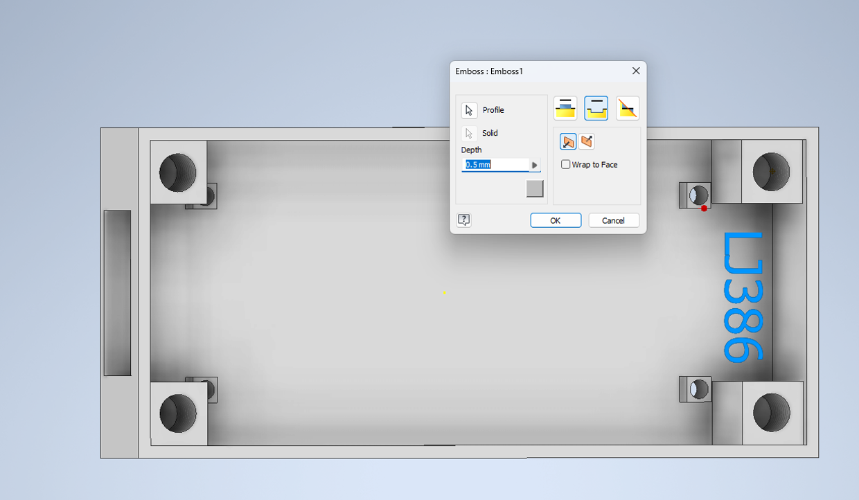
- Use the
Embossoption within theCreatetab to create the engraving. - Ensure that you have selected engrave option and set the depth to
0.5 mmas shown below.
Modifying the Lid
Using the skills you learnt in the lab so far, adjust the lid you created last week to ensure it matches the new box. Make sure your lid includes the following:
- Holes and/or threading to enable it to be securely fastened to the box.
- The use of a pattern.
- Engraved username.
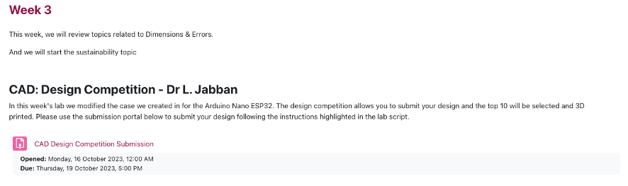
Design Competition
A few students expressed an interest in having their designs 3D printed which inspired this week’s design competition! You are able to submit the designs you worked on in the lab using the moodle submission portal and the best 10 designs will be 3D printed.
Entry Requirements:
- Both the case and lid have to be submitted as two STL files. Other formats will not be accepted.
- The design should include, as a minimum, all the features developed in this lab as well as at least two additional features.
- The design should include your username as an engraving.
- You may upload a 1 page pdf (<300 words) to describe your additional features.
Click on File -> Export -> CAD format and select the file type as STL.
Winner selection criteria:
- Accuracy of the created part
- Creativity in use of additional features
- Functionality (i.e. will you be able to actually use the case you made?)
- Can be 3D printed- if you are not sure about any features, ask the lab demonstrators.
Submission:
You can submit your design using the submission portal in week 3 of design skills, as shown below. The submission deadline is the 19th of October at 5pm.