Creating a simple part with CAD
Introduction
In today’s segment of the lab, we will explore the intricate design of PCB enclosures using Autodesk Inventor. Enclosures, often overlooked, play a pivotal role in safeguarding sensitive electronics and ensuring the longevity and reliability of a product. In the vast domain of electronics design, from consumer gadgets to high-tech industrial equipment, the right enclosure can make the difference between a successful product and a flawed one.
The part
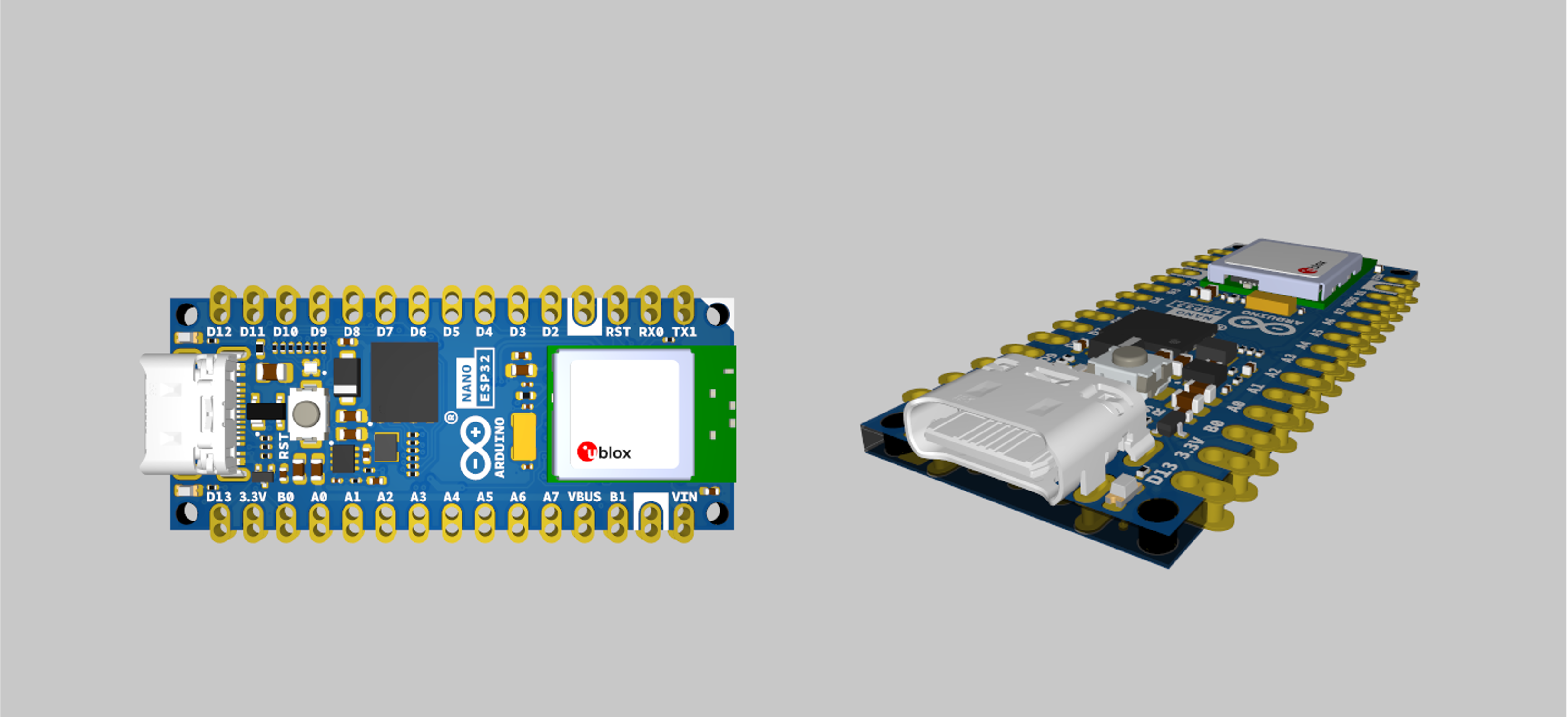
The part we will be designing is a very basic enclosure for an Arduino Nano ESP32, which is the microcontroller you will be using throughout the year. (You can read more about it here)
The Arduino Nano ESP32 features the NORA-W106, a module with a ESP32-S3 chip inside. This module supports both Wi-Fi® and Bluetooth® (5.0 and above), making it an ideal device for IoT development. The popular Nano form factor also makes it compatible with many hardware accessories.
Arduino Nano ESP32 is the first Nano board to feature a USB-C® connector!
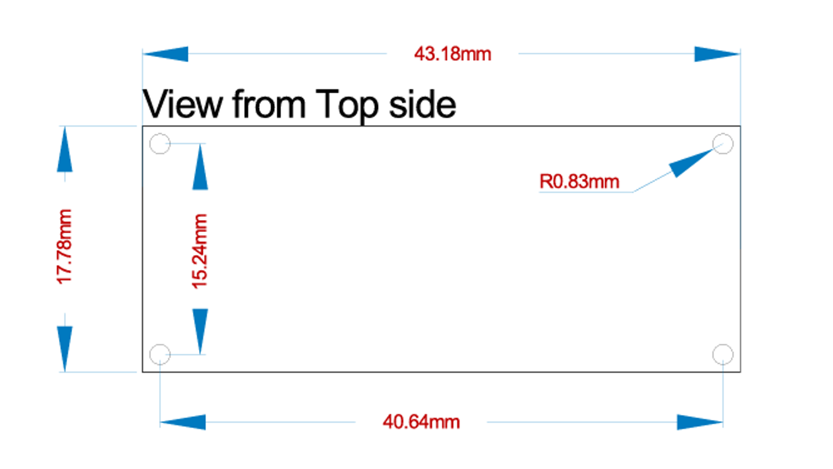
The mounting dimensions of the arduino are shown below.
Getting Started with Autodesk Inventor
This part of the tutorial focuses on getting you familiar with Autodesk Inventor before we start creating the part.
Creating a new file
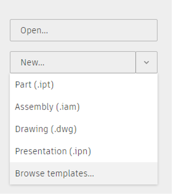
- To create a new part file, click on the arrow next to New and select
Browse templatesfrom the drop-down menu.
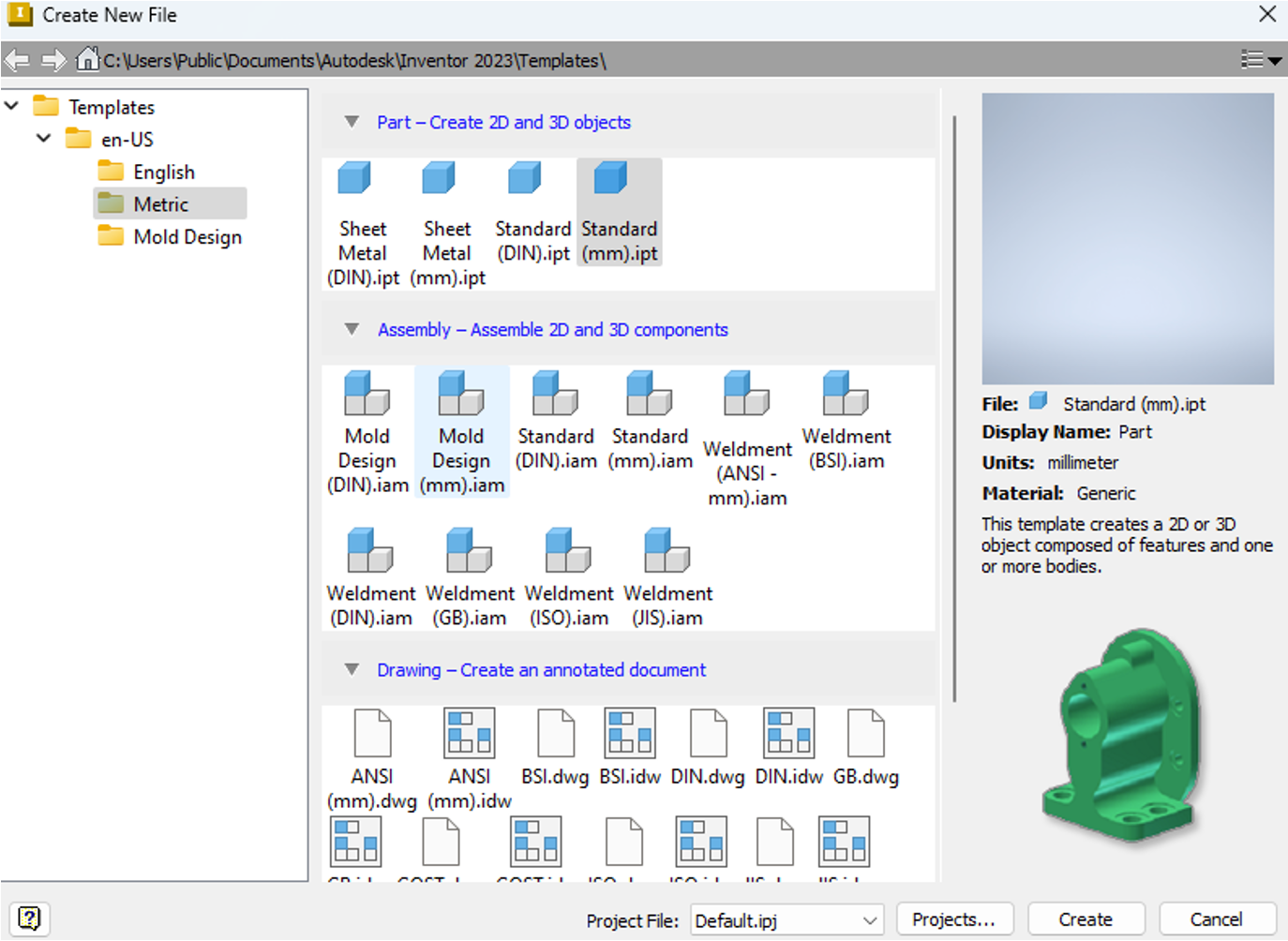
- A new window will open with a range of templates from you to choose from. Select
Standard (mm).iptto create a part, ensuring that the units are set to mm.
Getting Familiar with the Interface
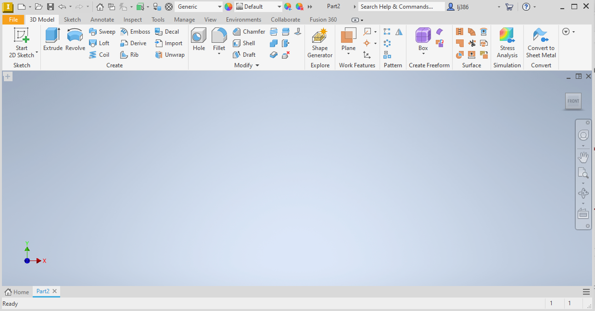
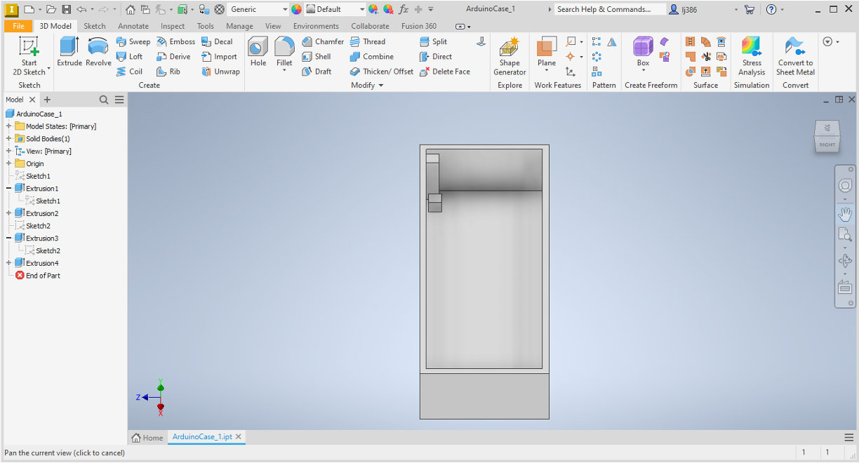
Once you have created your part, you should see something similar to the screenshot below.
Getting Started Videos
Below are some short videos created by Autodesk to teach some of the essential skills needed to use Autodesk Inventor. Please watch them before proceeding to the next step. You may wish to return to them afterwards to refresh your memory about useful shortcuts and tips.
Follow this link to watch Autodesk’s instructional video which provides useful overview information about autodesk inventor.
Follow this link to watch Autodesk’s instructional video which will help you get familiar with navigating the interface.
Follow this link to watch Autodesk’s instructional video on creating sketches.
Follow this link to watch Autodesk’s instructional video on creating parts.
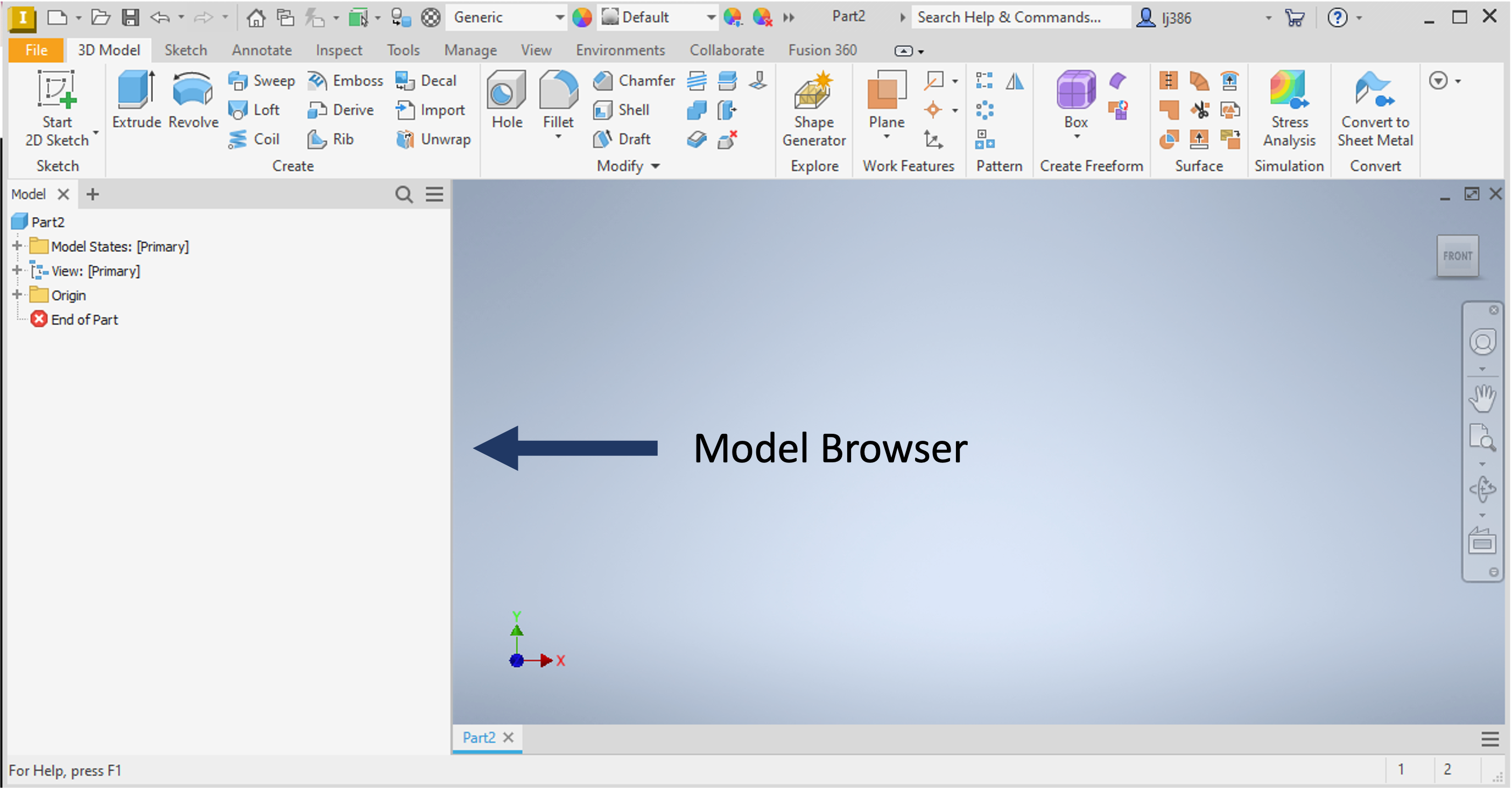
Viewing Model Browser
Now that you have watched the videos, you should have a better feel for how the user interface works. Before we get started, lets first make sure that the Model Browser is visible. This will help you keep track of the steps you are taking to create your part, and can be useful when you need to edit any features.
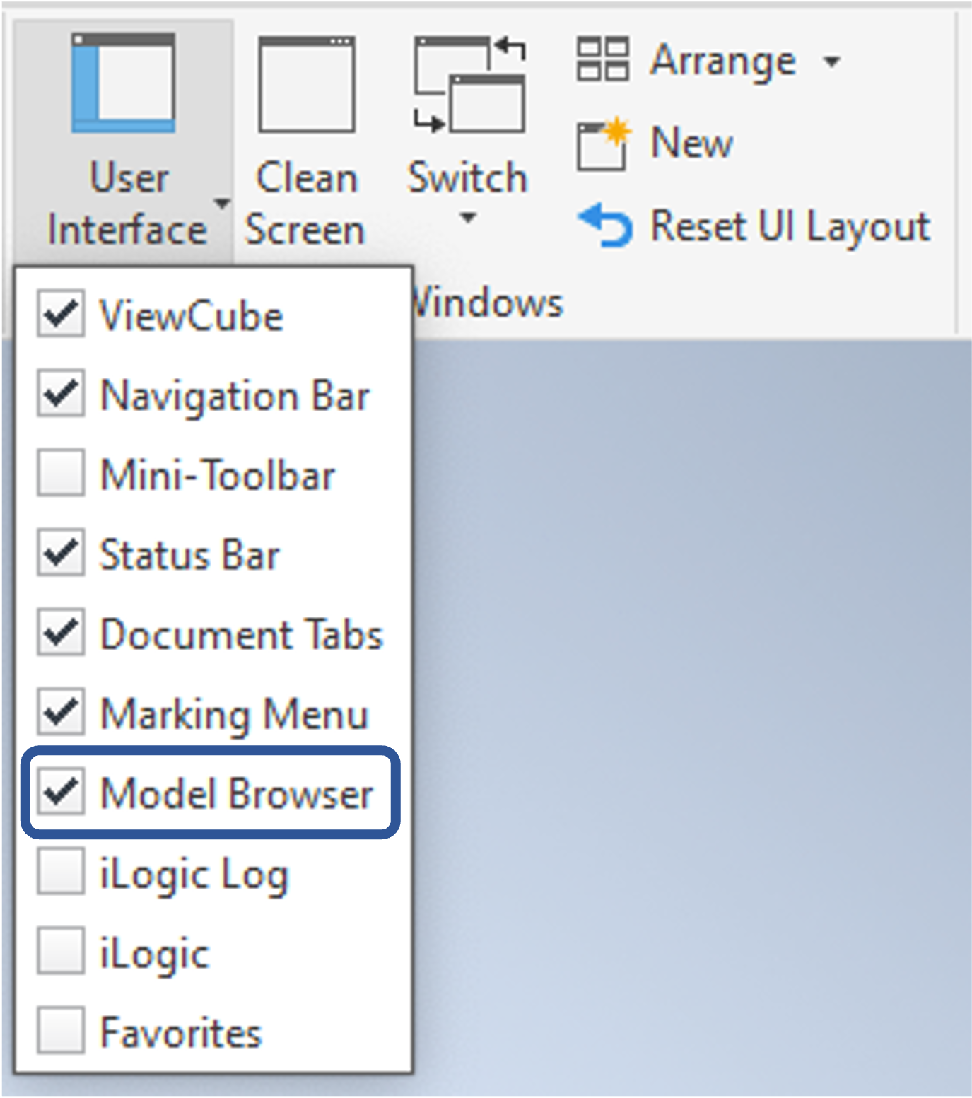
- Go to
view->User Interface, and ensure thatModel Browseris ticked, as shown below.
Creating a Sketch
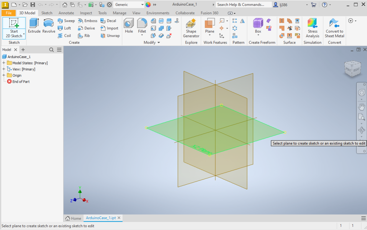
- Start with creating a sketch by pressing on the
Start 2D Sketchbutton. - Select the plane which you want to draw your sketch on. For this exercise, lets select the
XZplane, as shown below.
- Note that once you select the plane, the top panel will change to show options specific to sketching.

Rectangle Outline
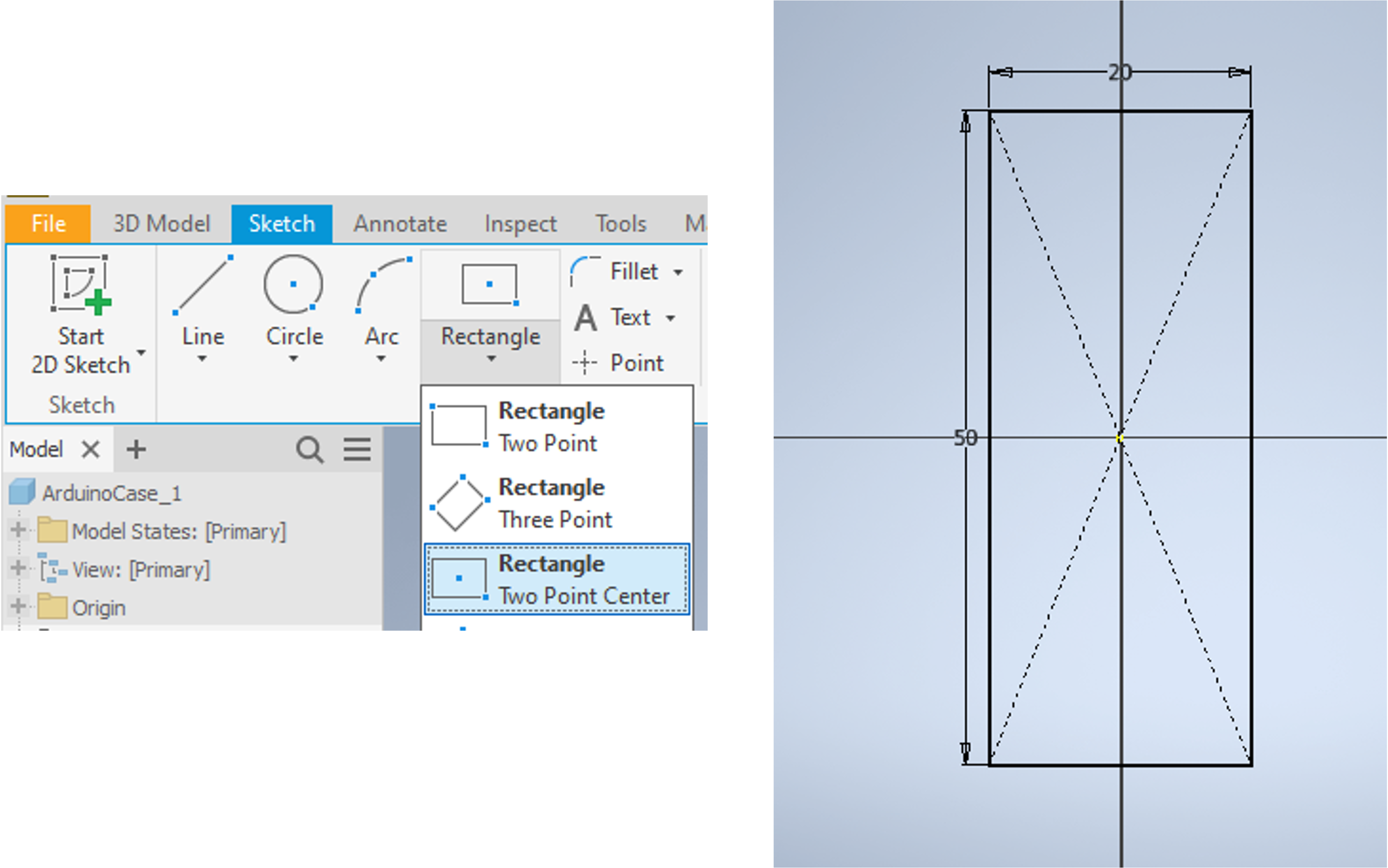
- Lets start with creating a rectangle centred around the origin. Within the
Createpanel, click on the arrow below theRectangleoption, and selectTwo point centre rectangle. - Place the first point at the centre, where the two axes intersect and then define the dimension of the longer side by typing
50mm. - press
Tabon your keyboard to enter the second dimension of20mm.
Wall
- Now that we have the outline sketch, lets create an inner one. The distance between the two will represent the wall thickness.
- Repeat the rectangle outline steps, but this time set the dimensions to
48mmand18mm.
- Go to
Tools->Measureto activate the measure tool. - Click on the inner side, followed by the adjacent outer side of the rectangle.
- The distance between them will be displayed.
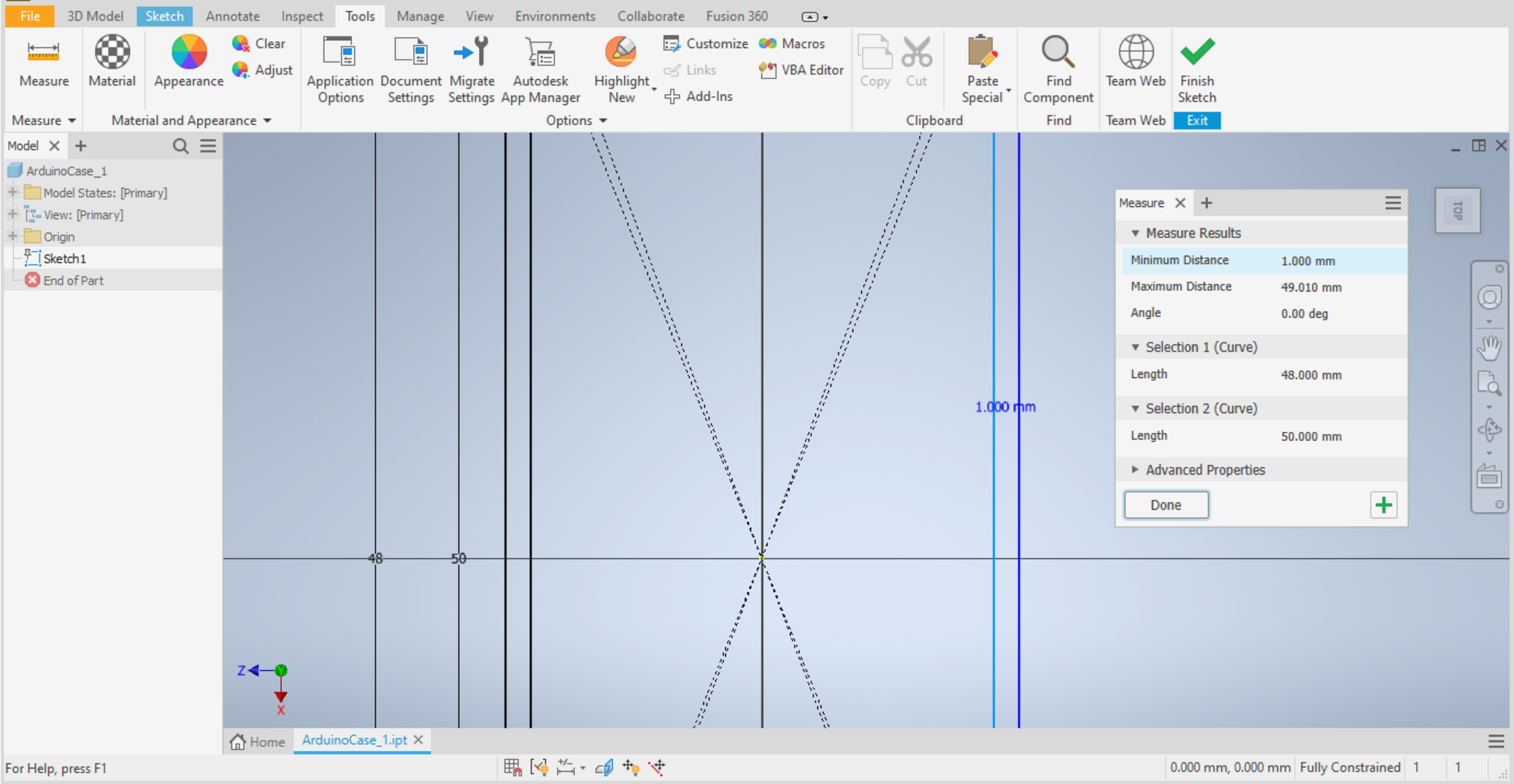
- Exit the sketch by clicking on
Finish Sketch.
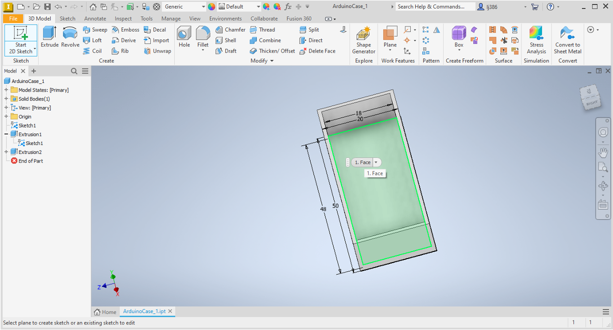
Extruding
Now that we have a sketch to work with, we can move from 2D to 3D by extruding. Extruding creates a 3D solid from an object that encloses an area, or a 3D surface from an object with open ends
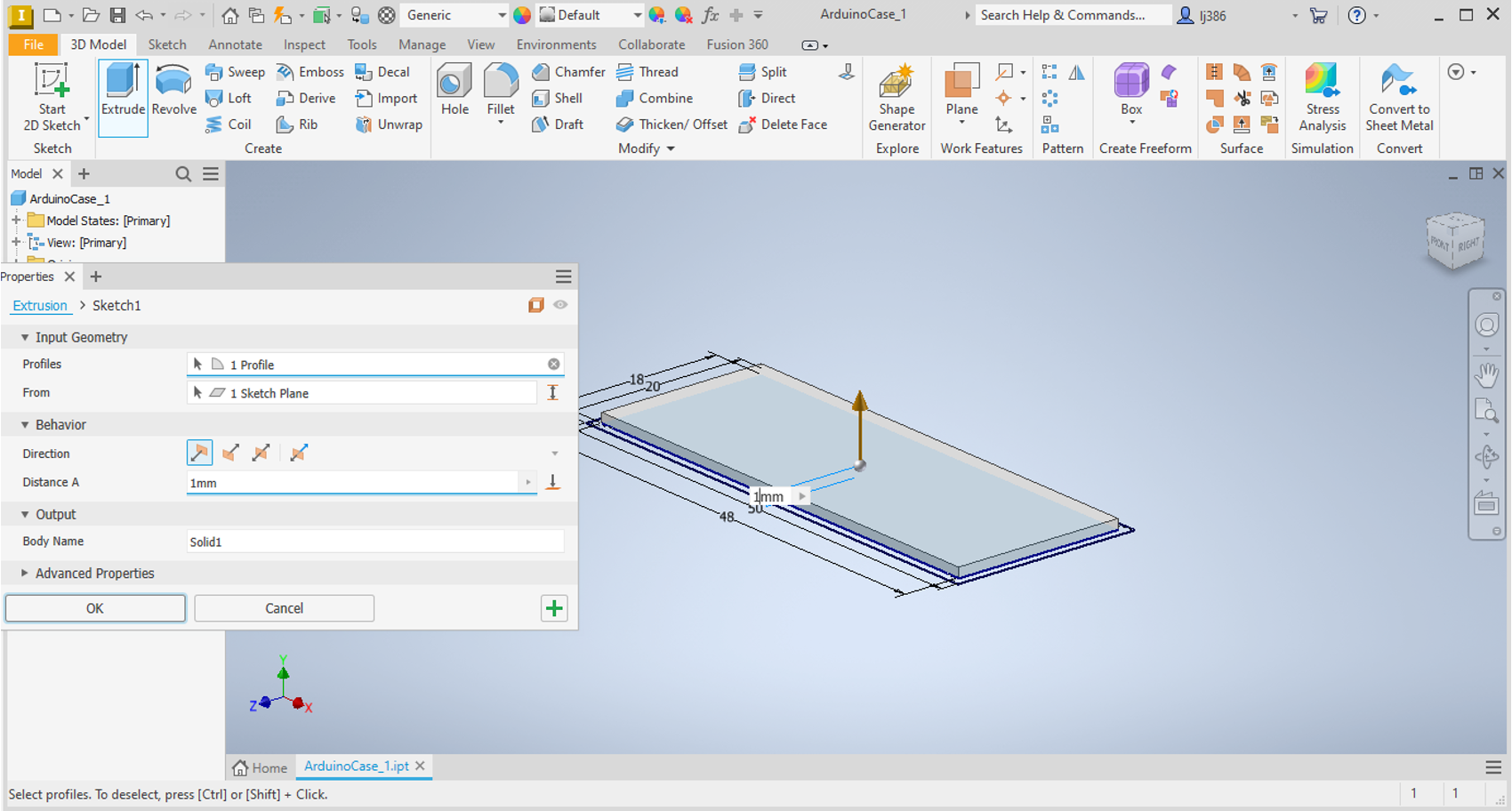
- Click on the
Extrudebutton. - You can now select the surface you want to extrude. Click on the inner rectangle to select it.
- Once you click on the surface a 3D representation will appear, allowing you to enter the extent by which you want to extrude. Type in
1mm. - Press
Enterto complete the extrusion.
Using the same sketch for a second extrusion
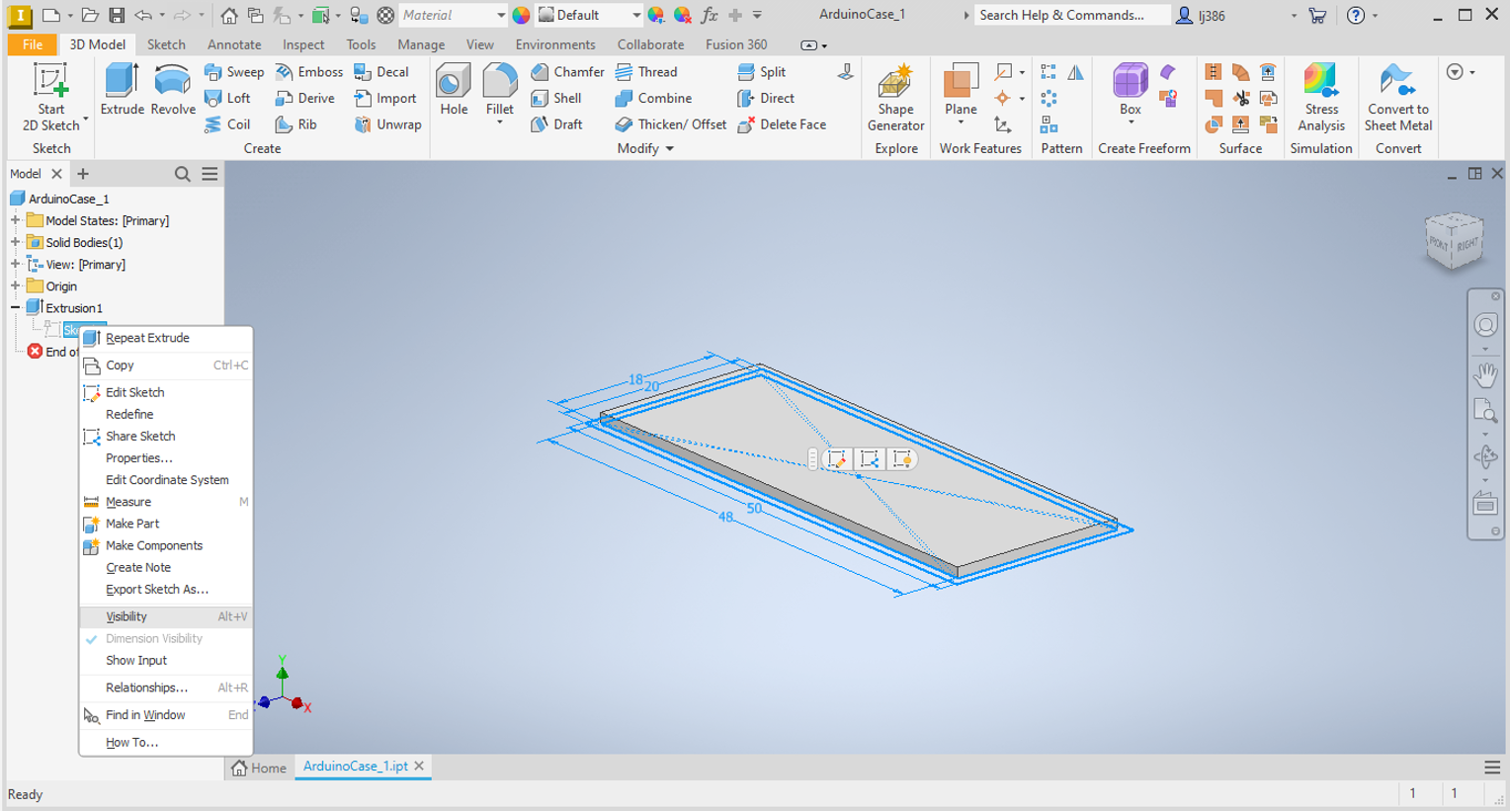
You may notice that the sketch we used to create the extrusion is no longer visible. In order to use the same sketch again, we need to make it visible again.
- In the
Model Browseron the right, click on the+next toExtrusion 1. - A greyed out
Sketch 1will appear. - Right click on it and select
Visibility.
- Now that the sketch is visible again, repeat the extrusion steps to extrude a
10mmwall using the surface between the outer and inner rectangle.
Adding Features
Now that we have a basic box, lets work on adding features to it. The features will be:
- Mounting for the Arduino
- Threading at the corners to enable a lid to be fastened
We will create a new sketch that includes the starting points for both of the features.
New Sketch
- Similar to what we did earlier, click on
Start 2D Sketch. - Click on the inner surface of the box to sketch on it.
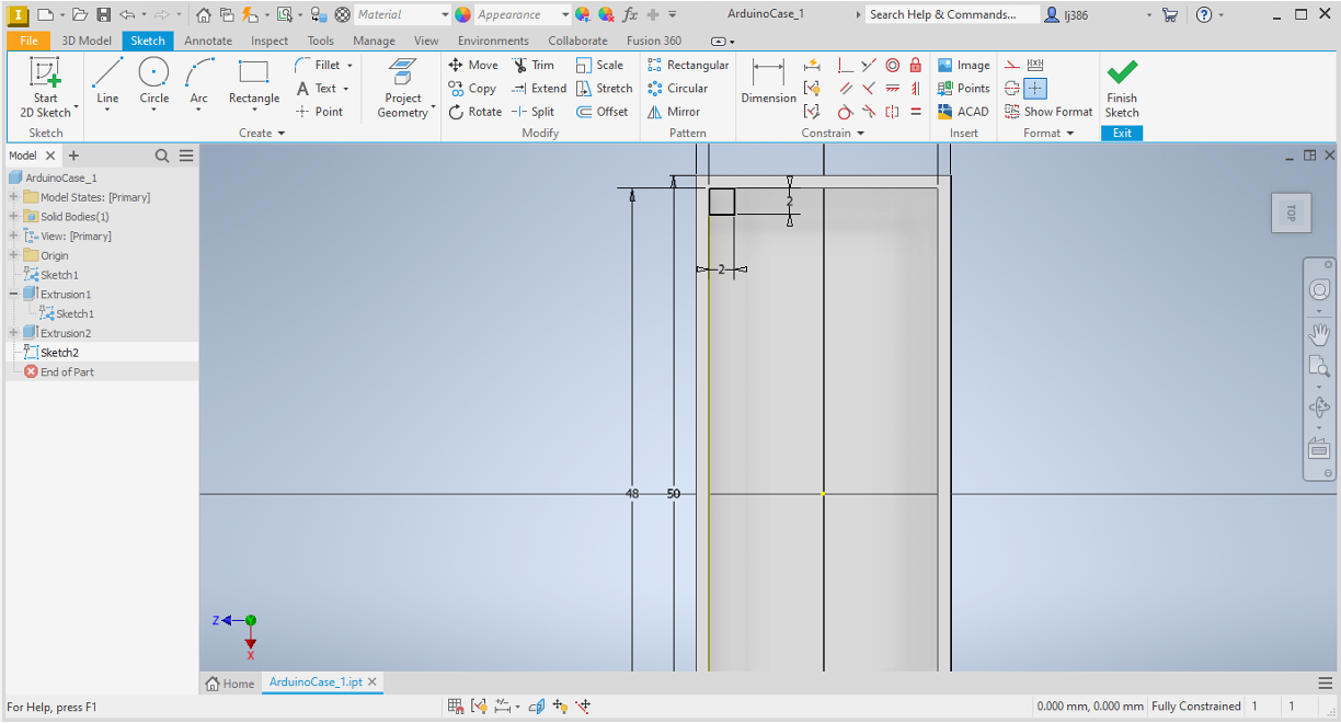
Threading at the corner (Square A)
- Lets create a rectangle at the top left corner.
- Within the
Createpanel, click on the arrow below theRectangleoption, and selectTwo point rectangle.
- Click on the top left inner point to define the first point.
- Set both dimensions as
2mm, you should end up with a square as shown below.
Mounting for the arduino (Square B)
- Using the arduino dimensions shown in the beginning of the lab script, calculate how far arduino mounting holes are from the centre of the arduino. You should have measurements for the
y-axisandx-axis. - Within the
Createpanel, click on thelineoption. - Place the first point at the centre of the rectangle and the second along the x-axis, defining the length as your calculated x-axis measurement.
- Repeat for the y-axis.
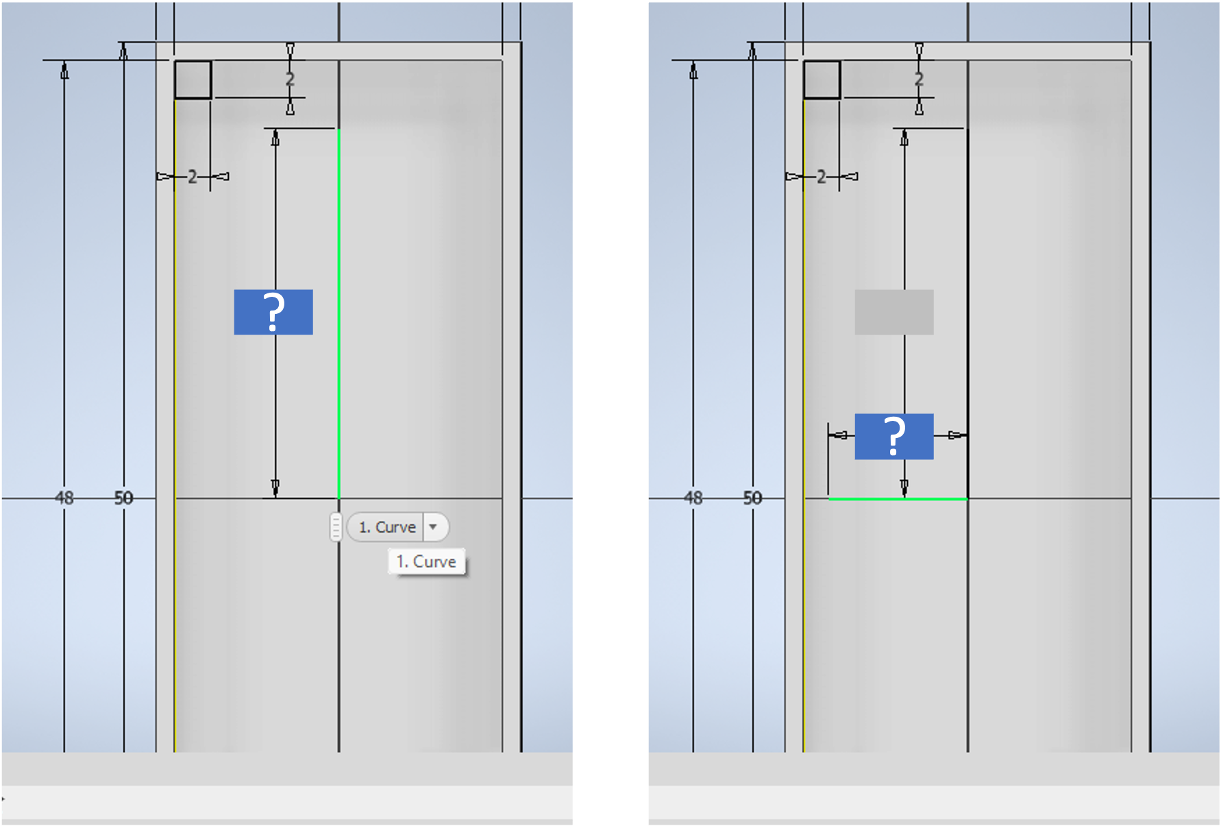
- The lines created will be used to guide the location of the mounting holes.
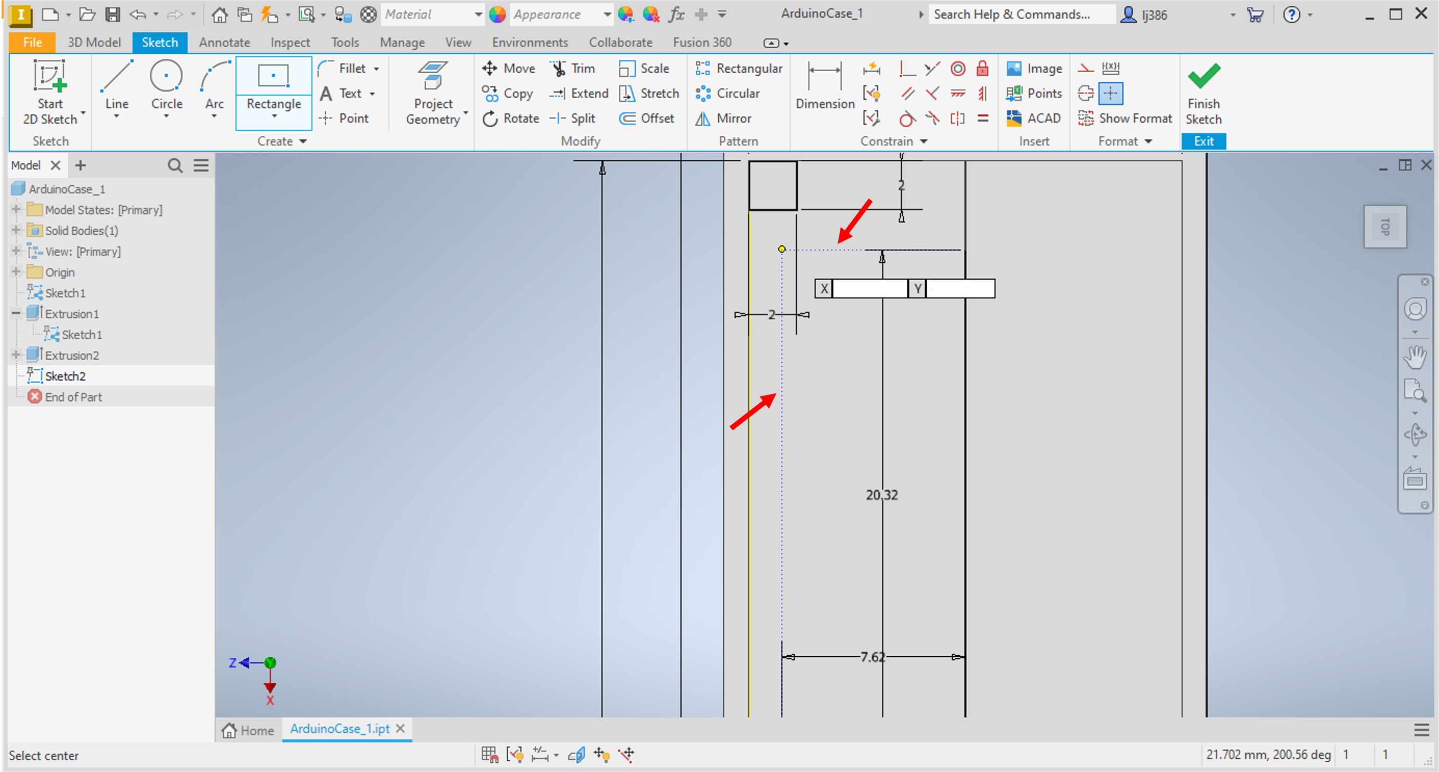
- Within the
Createpanel, click on the arrow below theRectangleoption, and selectTwo point Centre rectangle. - If you hover your mouse at the location shown in the screenshot below, guidance dashed lines will show indicating that the centre of the rectangle you are creating is at the defined x- and y- distances.
- Set both rectangle dimensions as
2mm. - Click on
Finish Sketch.
Extruding
- Extrude Square A by
8mm. - Toggle the visibility of the sketch.
- Extrude Square B by
2mm. - You should have something that looks like this
Adding Threading for fasteners
In order to use the structures we extruded, we need to add holes and threading so that a bolt or screw can be used to keep both the arduino and the lid in place. Lets check out how to do that:
- Switch to
Top Viewusing the navigation cube on the top right. - Within the
Modifypanel, click on theHoleoption. - A window will show with multiple options, you could hover over them to learn more. For now, we will stick to the default options.
- Click in the centre of the square top surface of the 8mm extrusion (A).
- Set the diameter to
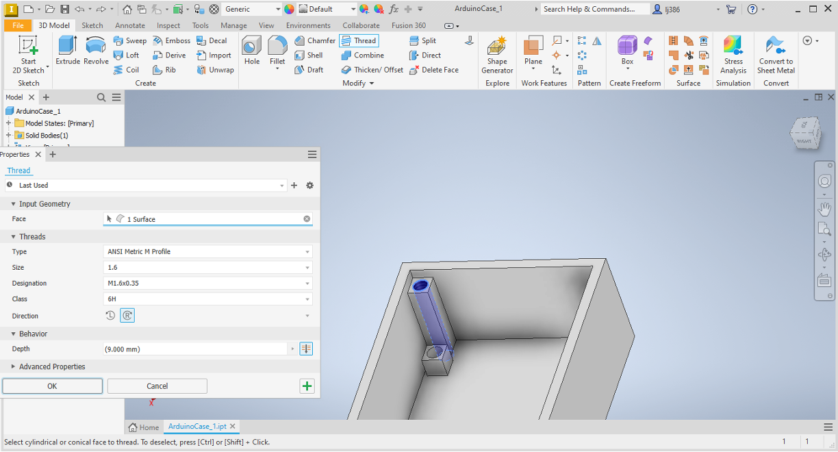
1.5mm. - Within the
Modifypanel, click on theThreadoption. - Click on the internal surface of the hole and ensure the settings are as shown in the screenshot below.
- Repeat for the second extrusion.
Mirroring the features
You may have noticed that we created the features in one corner only despite them being needed in the 4 corners. The reason behind that is that the usage of patterns simplifies the process considerably.
- Within the
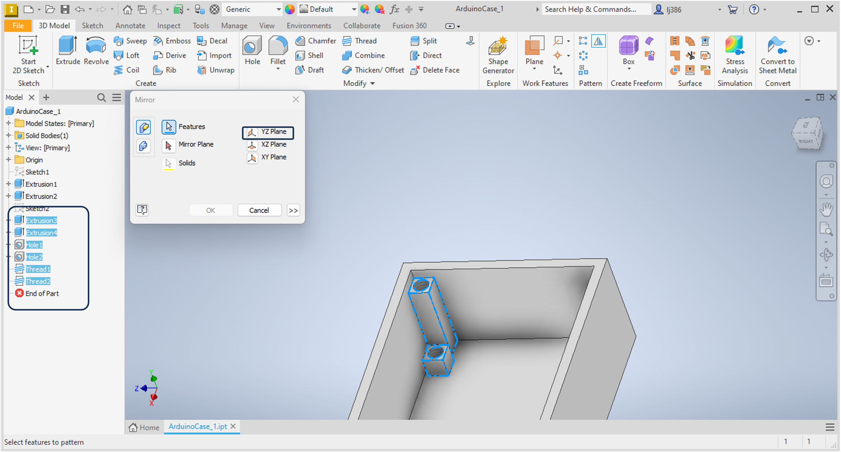
Patternpanel, click on theMirroroption. - A window will appear asking you to select features.
- Click on
Extrusion 3in the Model Browser. - Hold the
Shiftkey and selectThread 2to multi-select all the features in-between. - Click on
Mirror Planeand select theYZ Plane - Repeat with the
XY Plane, ensuring that you select the mirrored feature as well. - You should now have the mounting features on all 4 corners.
Design a Lid
Using the skills you learnt in the lab so far, create a new part that is the lid for this box.
Extension Tasks
The design used in this lab is rather simple to allow you to explore areas of improvement. Below are two suggestions you could try.
USB-C connection
You may have noticed that the box we created does not allow for the USB-C connection to be used. How would you modify the design to allow that? Explore the range of options available within Autodesk Inventor, remembering that if you hover on top of any of the buttons, a brief explanation will appear.
You can use the Measure tool with the CAD model of the arduino (downloadable using the button below) to measure any dimensions you may need.
More practical fastening options
The design uses M1.6 threading. Bolts of this size are not readily available. How would you modify the design to use larger threading? Note that the holes on the arduino do not allow for larger bolts to be used. What is an alternative way to secure it in place?