Creating an Assembly with CAD
Introduction
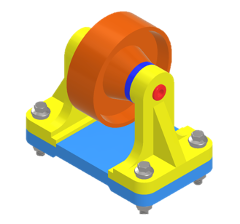
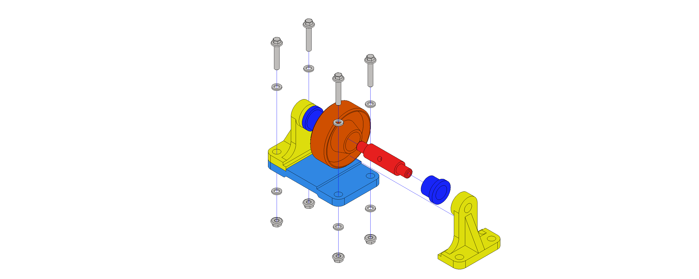
The aim of this lab session is to use pre-designed parts to create an assembly of the roller shown below. Assemblies are inventor files (.iam) that reference different parts and define the relationships between them to build an “assembled” component.
Once the assembly is done, an exploded view of the roller will be generated to illustrate the assembly sequence. This will be done using a presentation file. Presentation files (.ipn) are a file type in inventor used to [1]:
- Create an exploded view of an assembly to use in a drawing file.
- Create an animation which shows the step by step assembly order. The animation can contain view changes and the visibility state of components at each step in the assembly process. You can save the animation to a .wmv or .avi file format.
Downloading the parts
The parts used in the assembly can be downloaded from moodle using this link.
Creating the Assembly
Below are refresher videos if needed.
Please note that you can achieve similar results using the “joint” tool, as discussed in the lecture.
Creating an assembly file
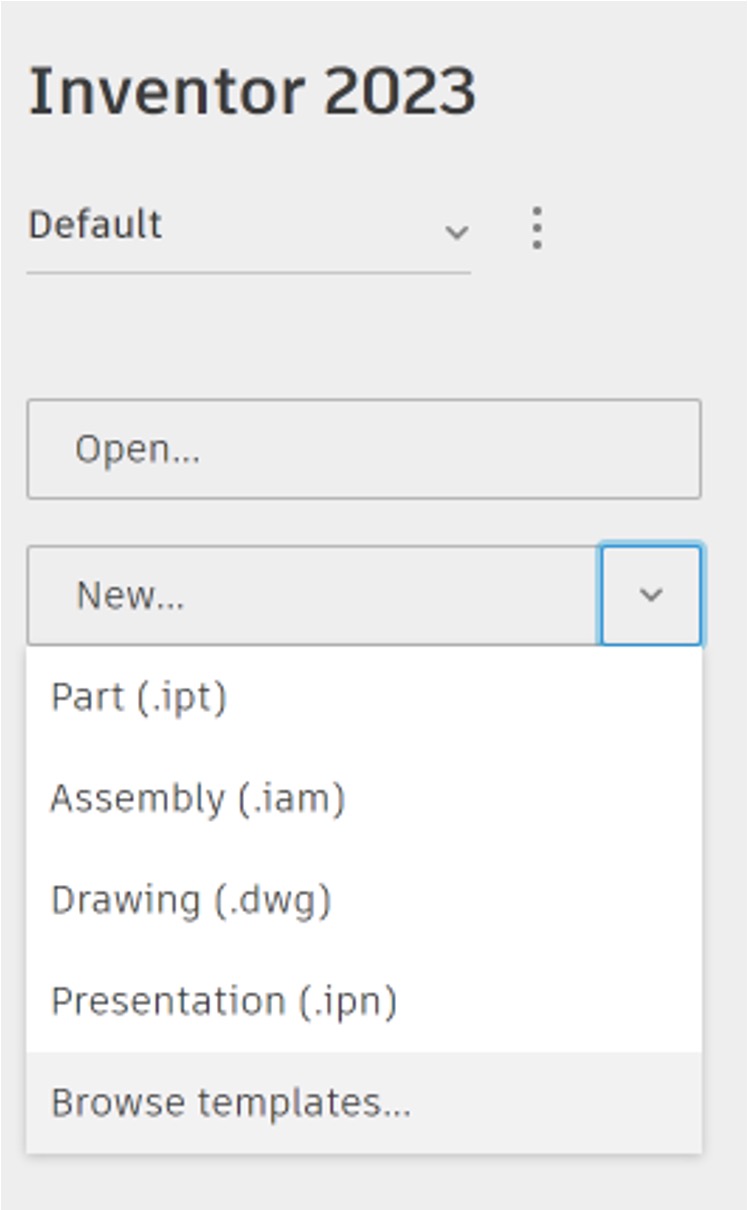
- To create a new assembly file, click on the arrow next to New and select
Browse templatesfrom the drop-down menu.
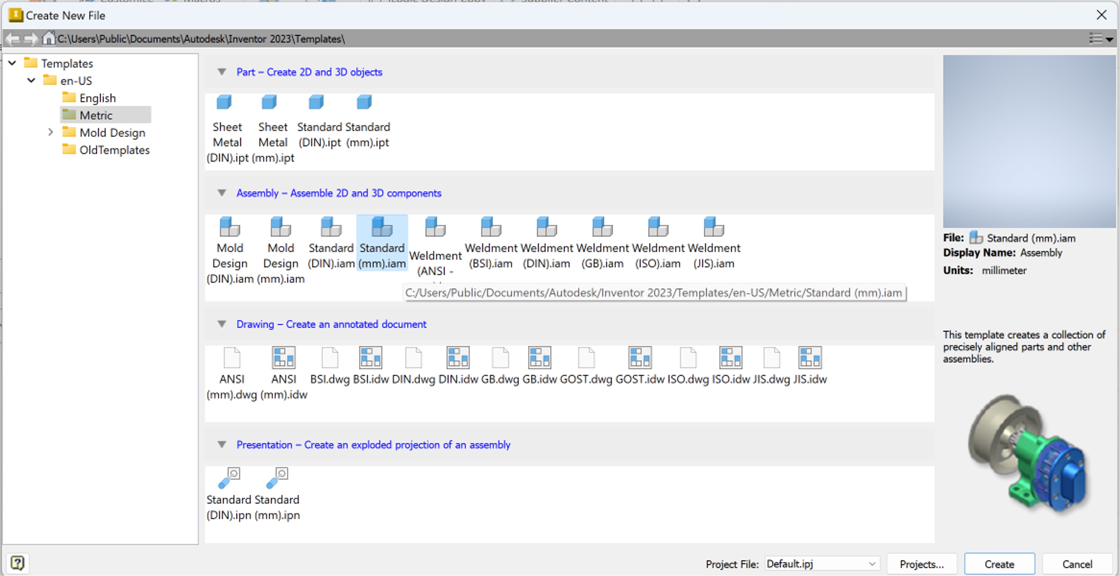
- A new window will open with a range of templates from you to choose from. Select
Standard (mm).iamto create an assembly, ensuring that the units are set to mm.
Adding components
- Use the
Placebutton to start the assembly by adding thebasemodel.
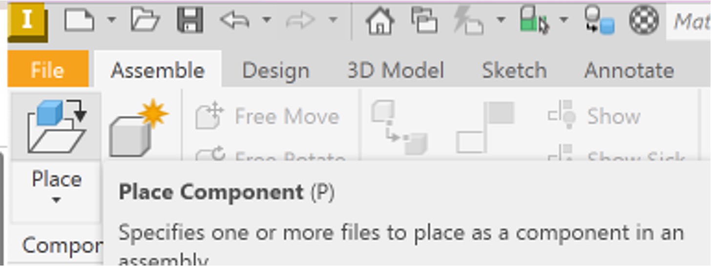
- Click anywhere on the working area to place the part.
Grounding the base
- It is good practice to align the main part to the origin of the assembly file.
- click on the
+next to Origin folders to see the origin planes of the assembly part and base.
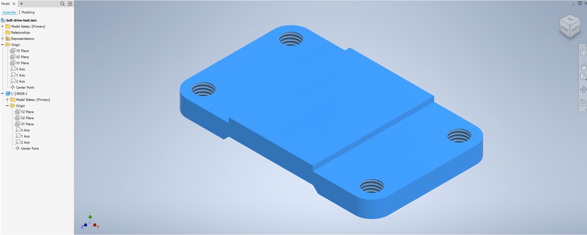
- Click on
Constrainin the top banner to apply the constraints. - Use the automatically selected
Mateconstraint type. - Click on the
YZ planewithin the assembly file. - Click on the
YZ planewithin the base file. - You will notice the base ‘snapping’ into position.
- Click
Apply.
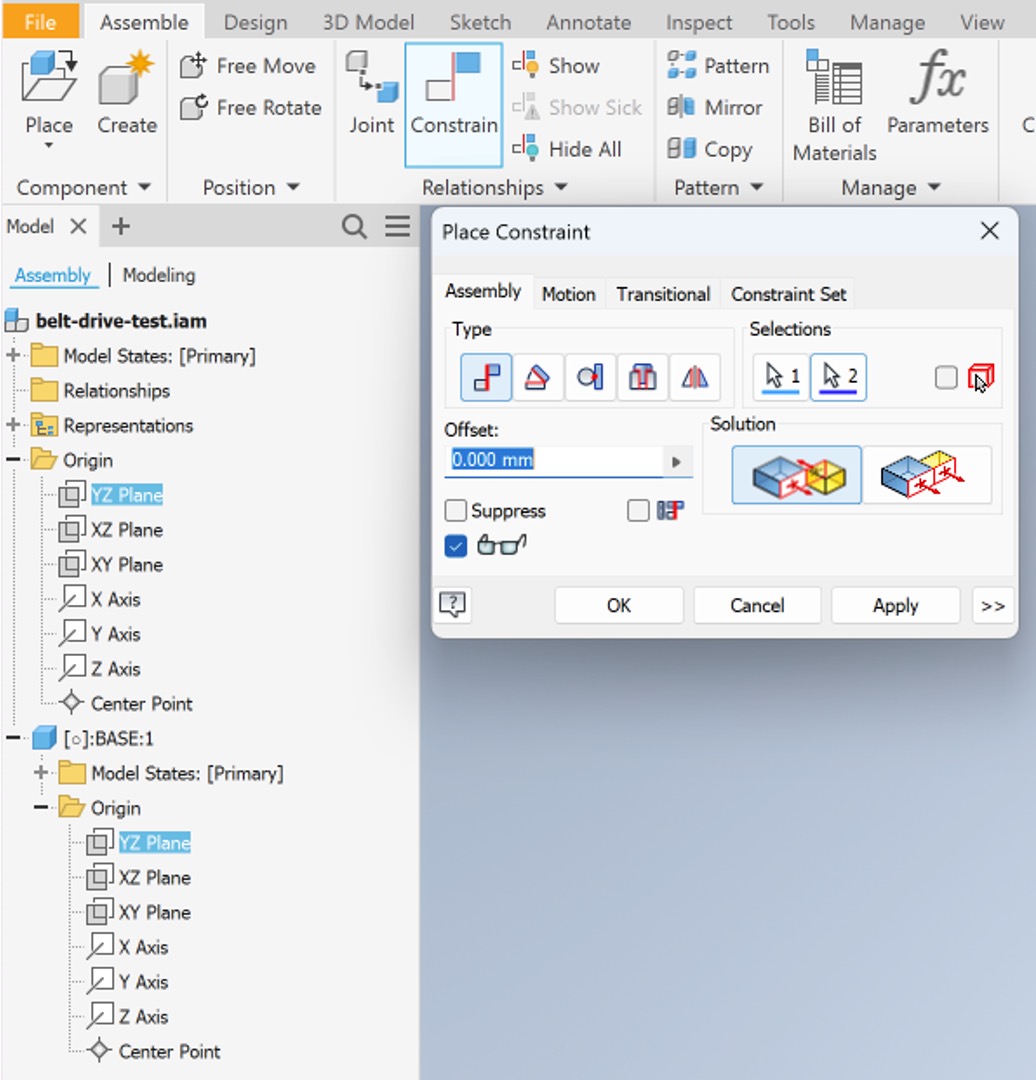
- Repeat the same for the
XZ planes, but clicking on theFlushoption withinSolutionsto ensure that the base is placed facing upwards and to avoid conflicting constraints.
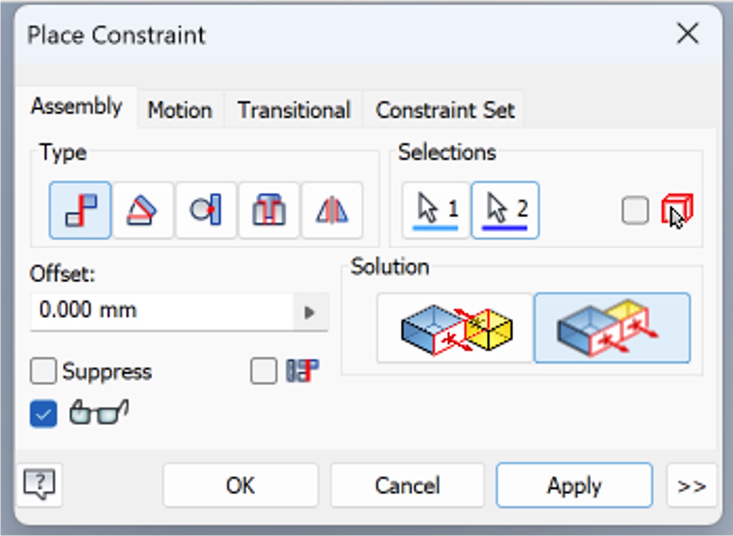
- Repeat for the
XY plane, choosing thematesolution.
Adding and constraining the first bracket
- Use
Placeto add the first bracket. - Note that you can use
Free MoveandFree Rotateto move the part to make it easier to apply the constraints. - Click on
Constrain - Select the centerlines of the bracket and base, as shown below. This is done by hovering next to the hole until the centerline appears.
- Note the change in the solution options.
- Click Apply.
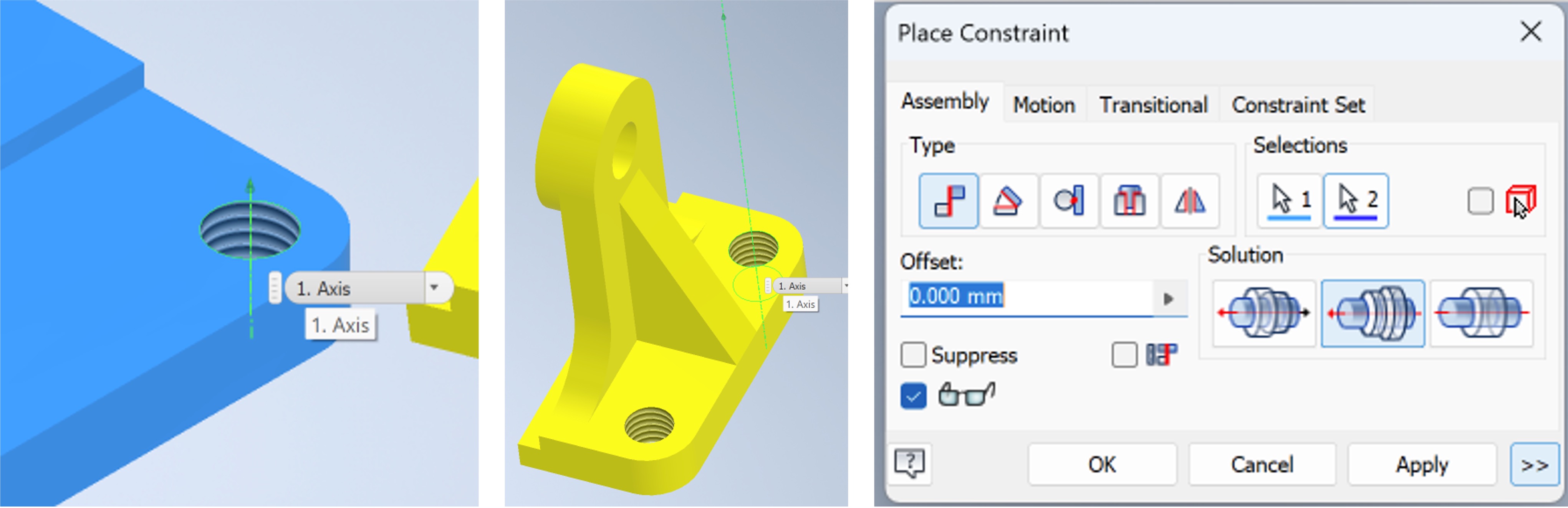
- Repeat the process with the second threading.
- Try moving the bracket and you can notice that it will only go up and down relative to the base, keeping the threadings aligned.
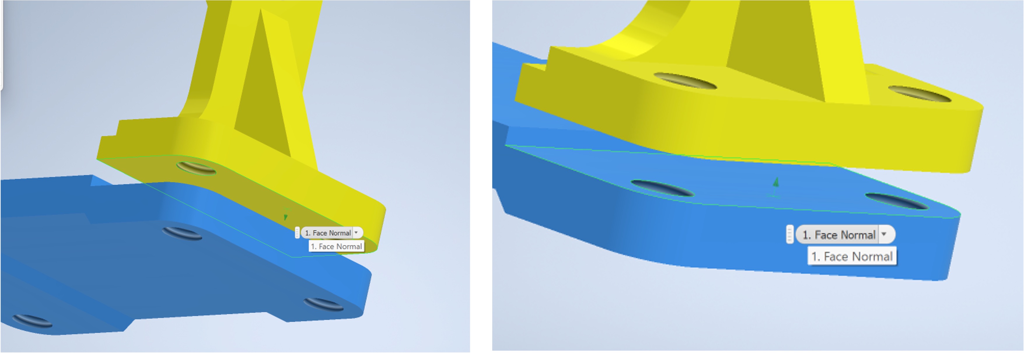
- Use the
mateconstrain to align the bottom face of the bracket to the top face of the base, as shown below.
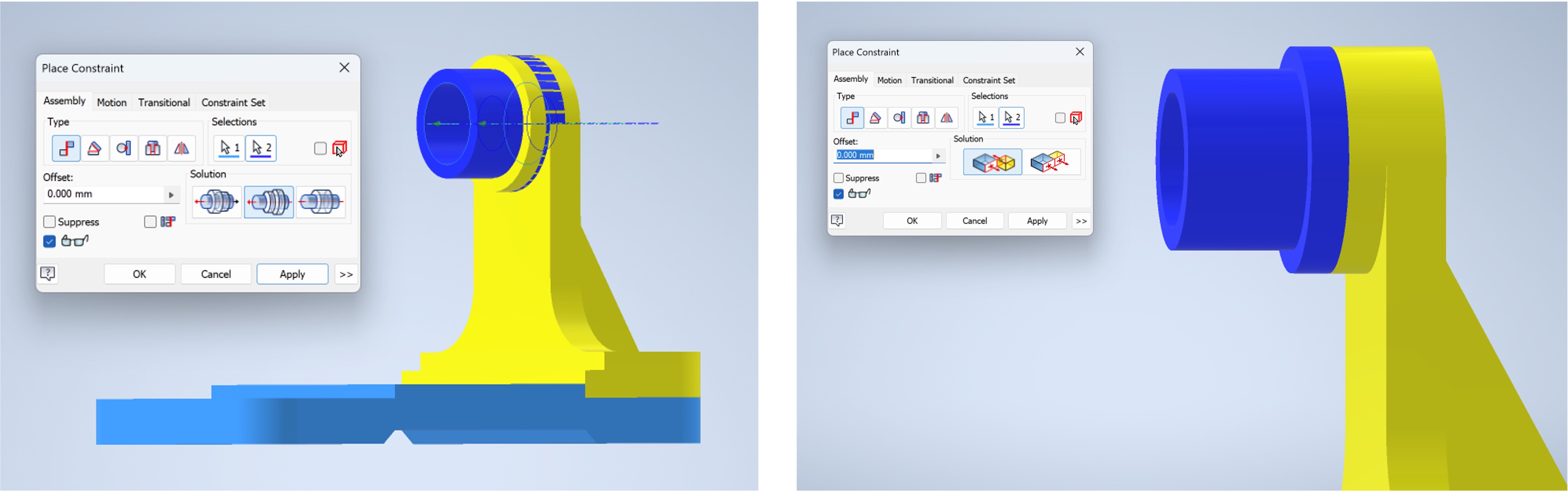
Adding and constraining the bush
- Use
Placeto add the bush. - Align the centres as shown in the screenshot below. Note that
alignedis chosen within theSolutions. - Mate the end of the bush to the bracket as shown below. Make sure that you are selecting the currect surfaces.
- Click apply.
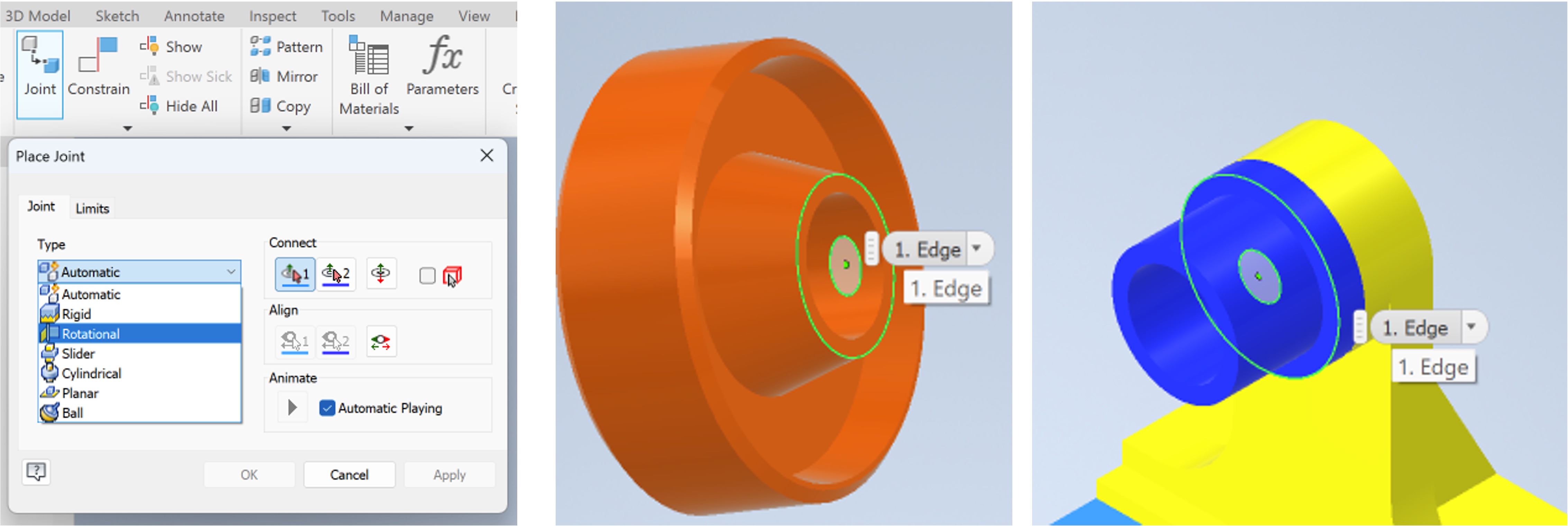
Adding the roller and defining a joint
- Use
Placeto add the roller. - Click on the
jointtool and select theRotationaltype to allow the roller to rotate around the bush. - Select the faces as shown below.
- Click apply.
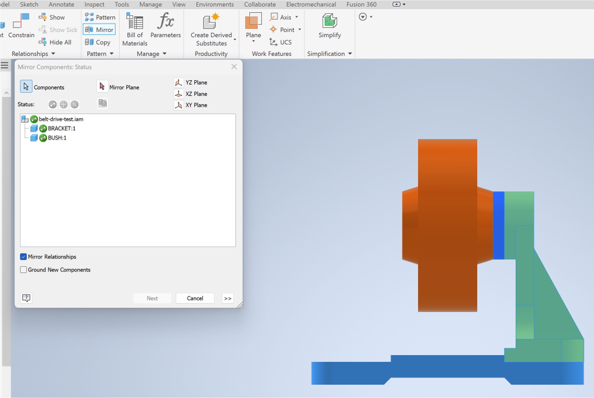
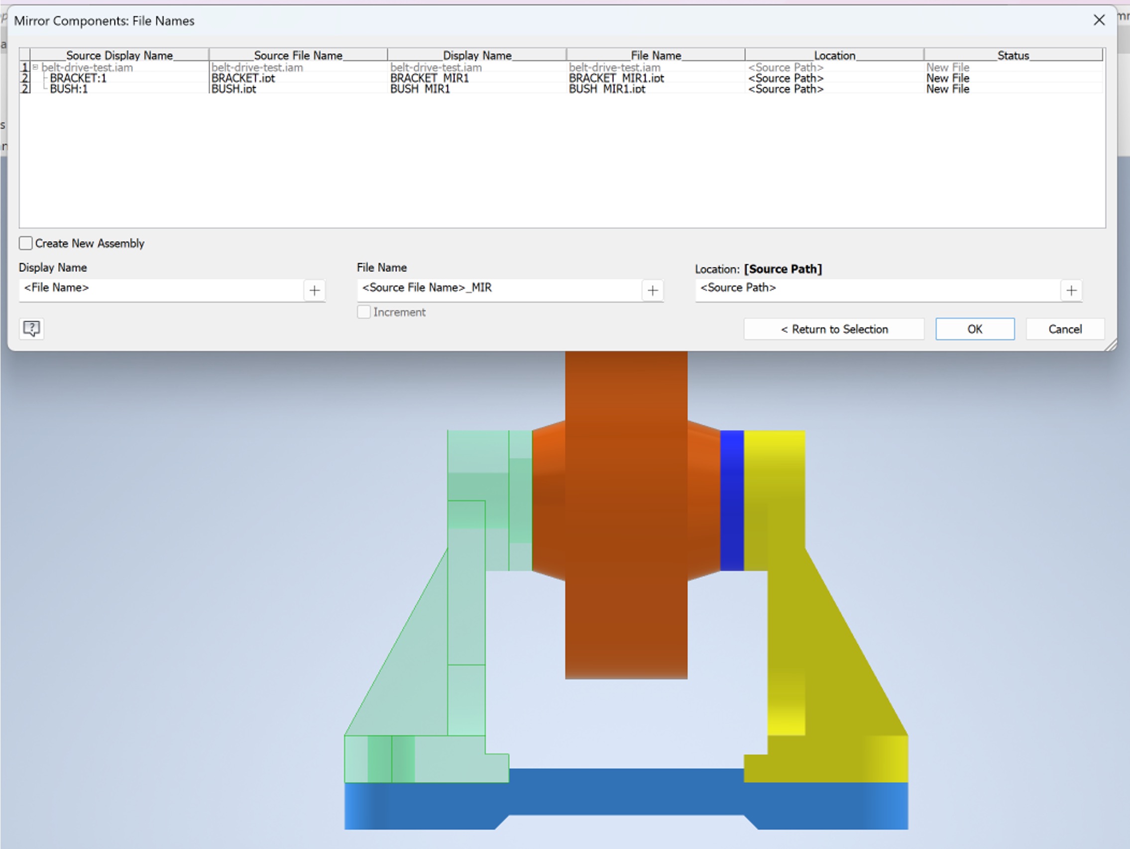
Mirroring the bracket and bush
- Given that the other side of the assembly is a mirror of what just assembled, the
Mirrortool within thePatterntab can be used. - Select the bracket and bush as the components.
- click on
Mirror plane. - Select the mirror plane to be the base’s YZ plane.
Adding and constraining the shaft
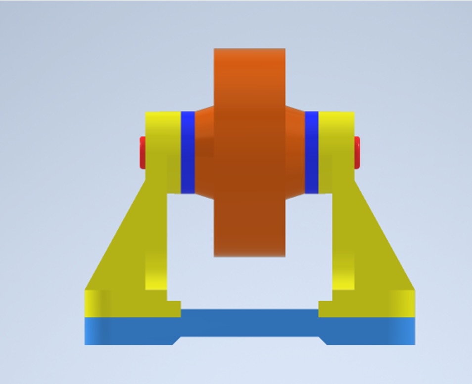
- Using what you have learnt so far, constrain the shaft to result in the assembly shown below.
- There are multiple ways to achieve this, feel free to use whichever you prefer.
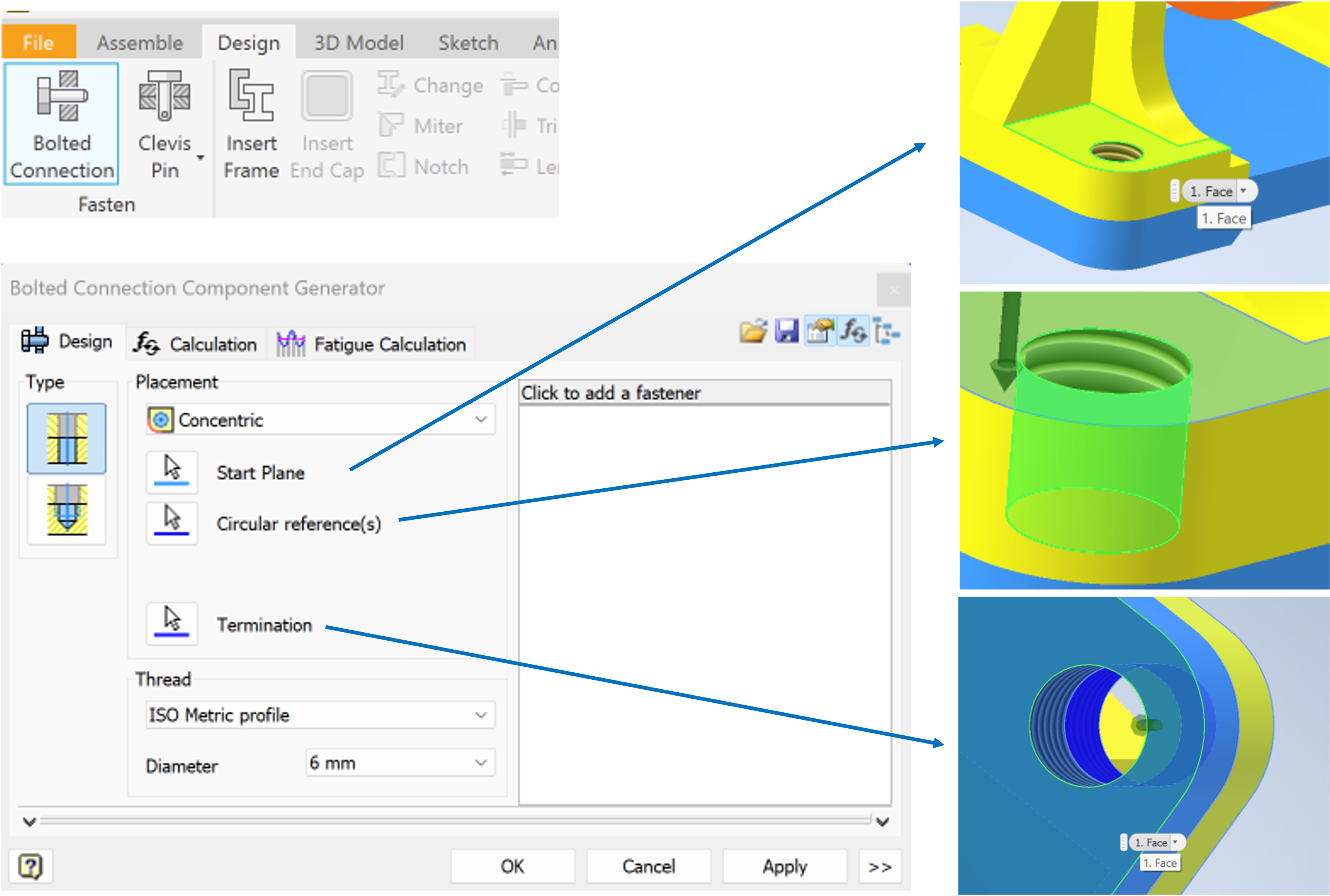
Adding fasteners
The Content Centre within Autodesk Inventor allows for the addition of fasteners to be automated.
- Within the
Designtab, click onBolted connection. - Choose
Concentricfrom thePlacementdrop-down menu. - Choose the start plane, circular reference, and termination plane, as shown below.
- Press
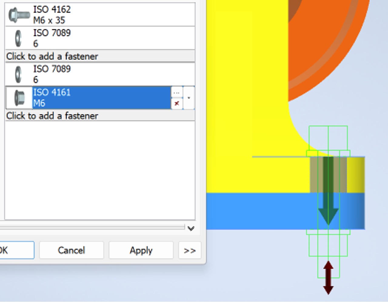
Click to add a fastener. - A pop up window will appear with several options. You can filter them by selecting the
ISOstandard andHex Head- Flanged Boltcategory.
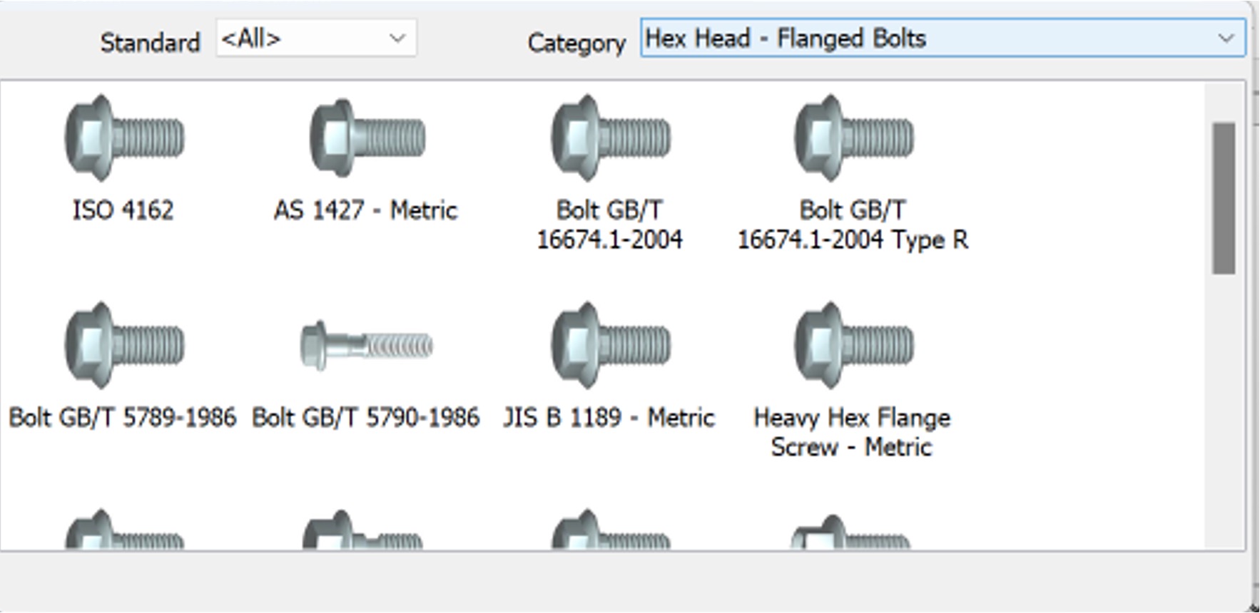
- Select the
ISO 4162bolt. It should appear on the list of fasteners. - Note that a thicker line is present separating the components you can add on either sides of the surfaces.
- Click on the top
Click to add a fastenerto add a washer. - Click on the bottom
Click to add a fastenerto add a second washer.
- Click on the bottom
Click to add a fastenerto add a nut. - By the end of this step you should have something that looks like the screenshot below. If it does, click
Apply. - Use
mirrororpatternto add the rest of the bolts.
Adding Username
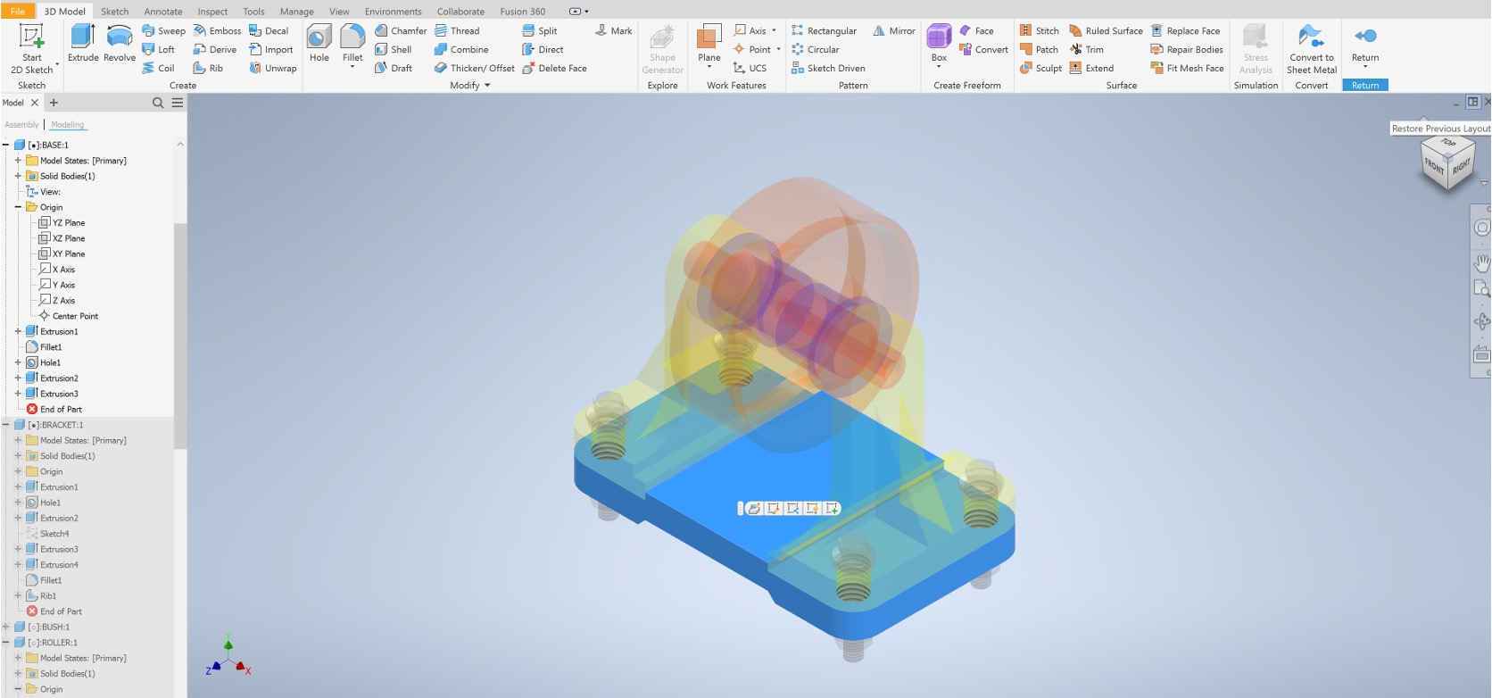
Do not forget to edit on of the visible parts to add an engraving with your username. You are able to edit parts while within the assembly environment.
Double click on the part you wish to edit to enter the isolate mode and use the 3D modelling ribbon used in the previous CAD lab.
Creating an Assembly Presentation
Below is a refresher video if needed.
Creating a presentation file
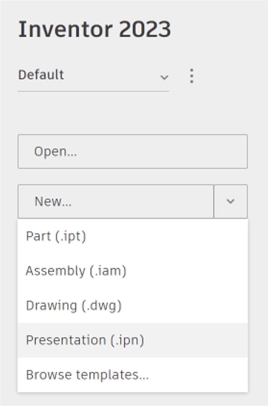
- To create a new assembly file, click on the arrow next to New and select
Presentation (.ipn)from the drop-down menu.
Placing the Assembly
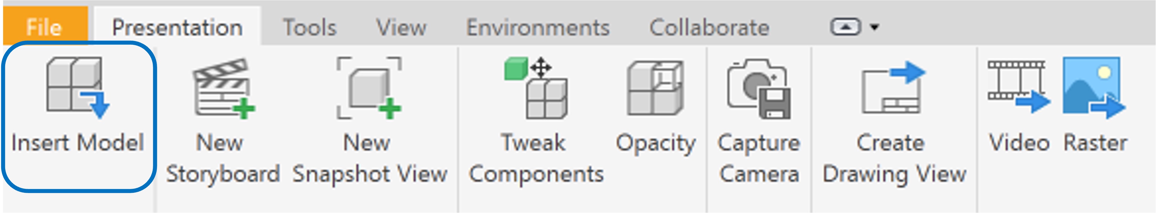
- Use the
Insert Modelbutton to add the assembly created earlier.
Creating the exploded view
- while pressing
Controlon your keyboard, select the 4 nuts added below the base. - Click on the
Tweak Componentsbutton and select the arrow parallel to the direction of the nut.
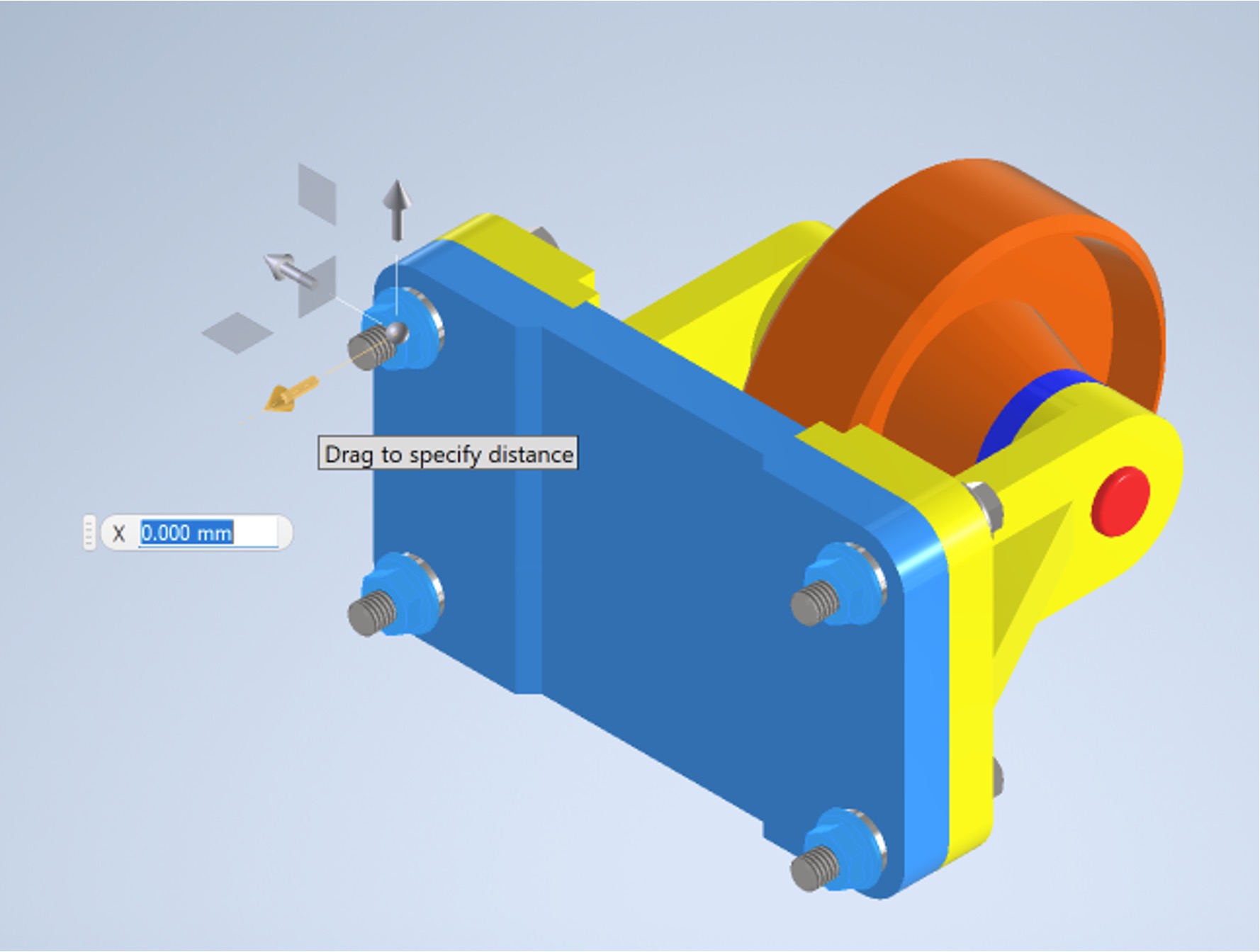
- Move the nut out by
75 mm. - Repeat with the washers, moving them by
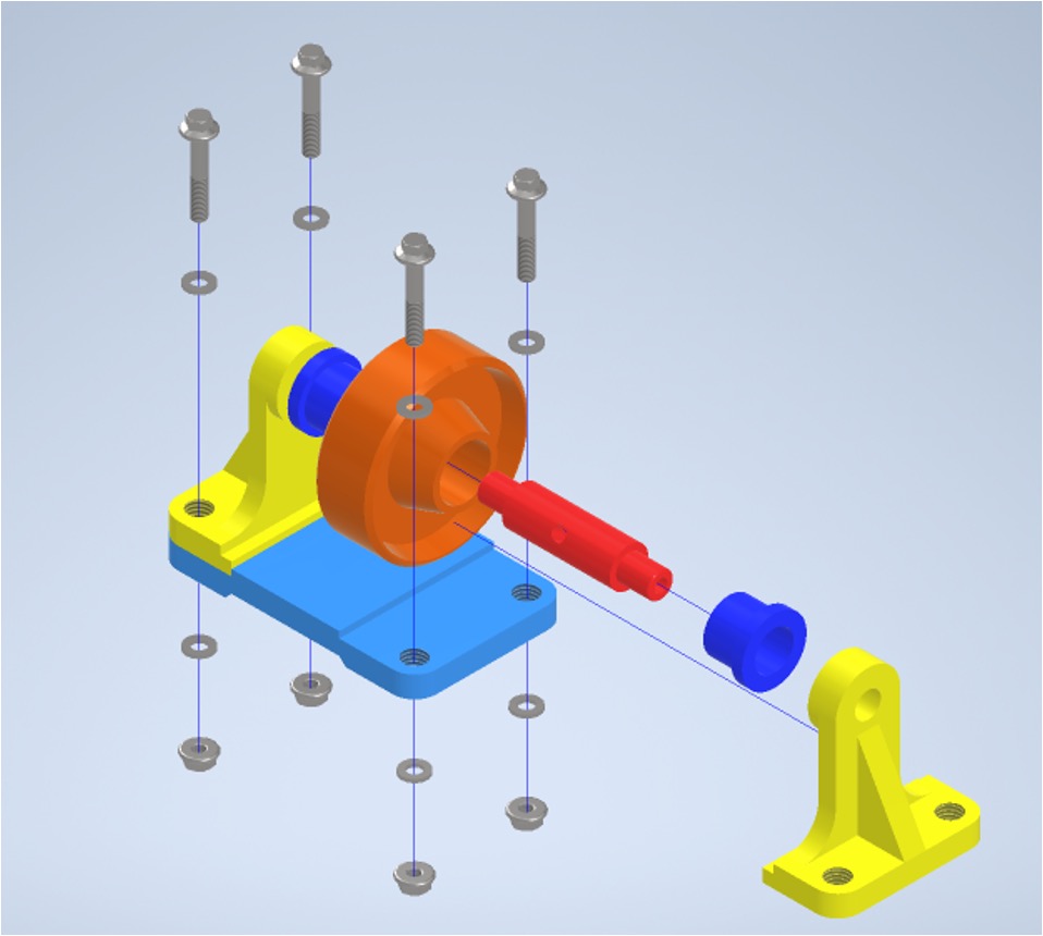
35 mm - Proceed with moving components until you get the exploded view shown below
Exporting an illustration snapshot
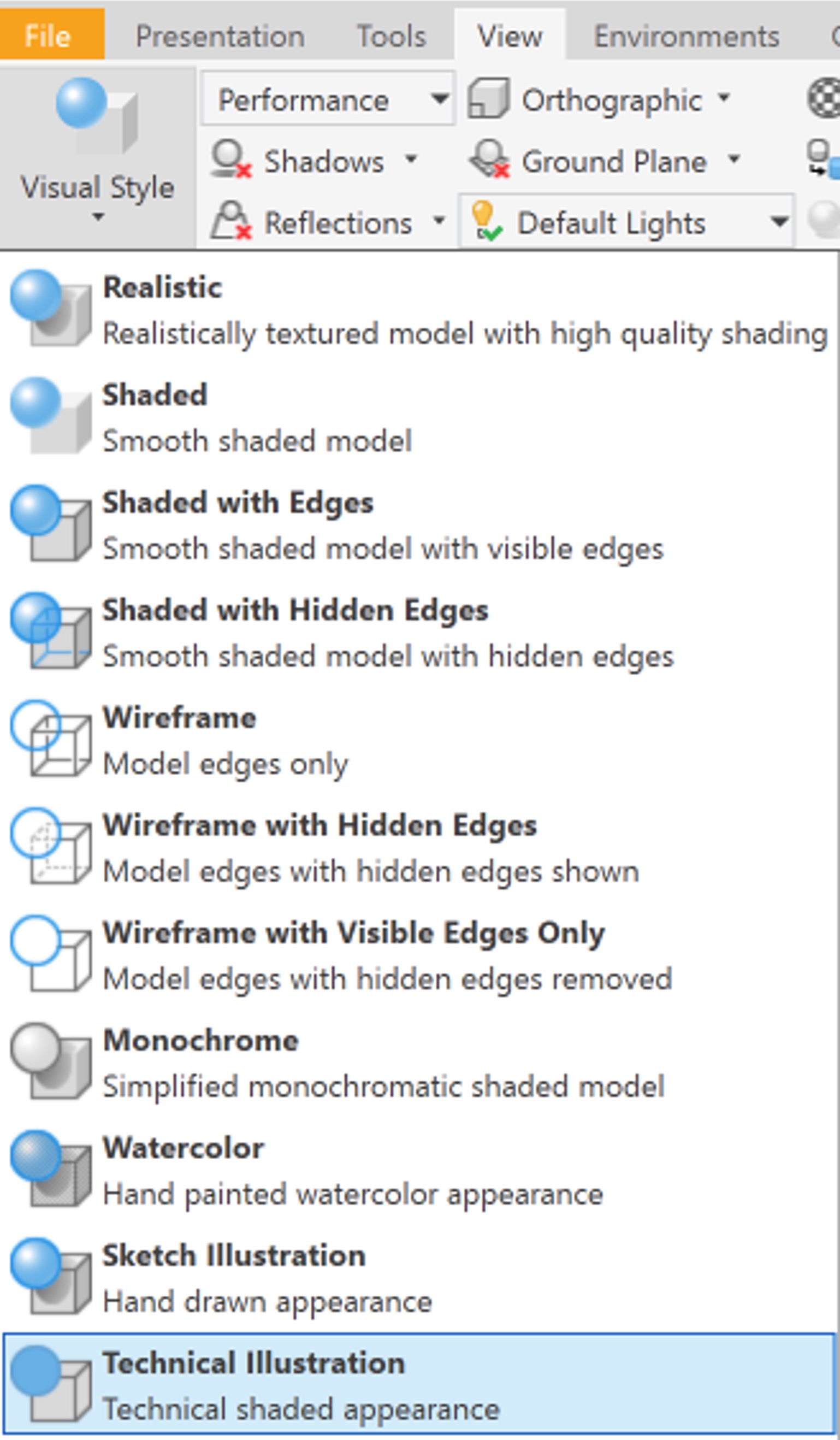
To export a cleaner view of the assembly, you could change the visual style to technical illustration.
- Within the
viewpanel click onVisual Styleand selectTechnical Illustration.
- Move the assembly to get the view you want.
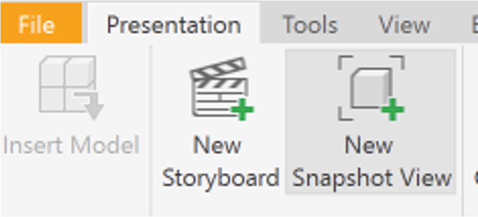
- Click on
New Snapshot Viewto capture the current view. It should get added to the panel on the right side.
- To export it, click on
Rasterand adjust the settings as you wish. You may wish to select thetransparent backgroundoption

The final result should look something like this:
Application task
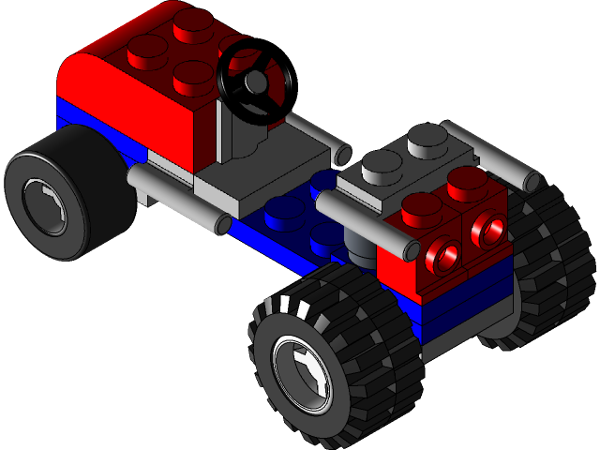
You can follow this link to download the parts for the application task. They are lego parts, enabling you to be creative in how you assemble them. However, below is a picture of a possible assembly should you wish to follow it.
References
[1] https://help.autodesk.com/view/INVNTOR/2023/ENU/?guid=GUID-94B779C0-6B2B-499A-A4F9-2E4BAB49712F
[2] Roller files designed by ROHAN GUPTA
[3] LEGO cad files designed by Hother - CPH Carpentry