Oscillator and AC Waveform Measurements
Introduction
This practical exercise introduces you to connecting up an op-amp integrated-circuit on a breadboard and using it as a voltage comparator to build an oscillator, i.e., source of AC waveforms. Alternatively, if you are work-ing off campus set up the circuit as a circuit simulation and make the required measurements on the simulated circuit output.
All the theory that you will require to do this laboratory is presented within these notes.
Op-amp as a voltage comparator
A voltage comparator (usually just called a comparator) is essentially a fast op-amp operated in an open-loop configuration; that is, without a feedback resistor, R2, between the output and the inverting input to reduce the gain, as shown in .
As with the op-amp configurations, the comparator has +VS and –VS supply voltage connections (see a), but these are normally omitted (see b) to reduce the clutter in circuit diagrams where the focus is on the function of a circuit.
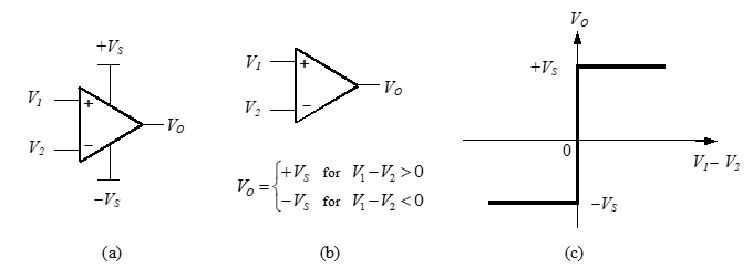
The relationship between the input and output voltages of an ideal comparator, termed the transfer characteristic, is expressed mathematically in b and illustrated graphically by the VOUT versus VIN graph in c.
If $V_1$ is greater than $V_2$, i.e., $V_1 - V_2 > 0$, the output voltage is $+V_s$. If $V_1$ is less than $V_2$, i.e., $V_1 - V_2 < 0$, the output voltage is $-V_s$.
\[\begin{equation} V_o = \begin{cases} + V_s & \text{for } V_1 - V_2 > 0 \\ - V_s & \text{for } V_1 - V_2 < 0 \end{cases} \end{equation}\]A comparator with the inverted transfer function, as in $\eqref{inv-transfer-func}$, may be obtained by simply reversing the input connections, so that $V_1$ is connected to the (-) inverting input and $V_2$ to the (+) non-inverting input.
\[\begin{equation} V_o = \begin{cases} + V_s & \text{for } V_1 - V_2 < 0 \\ - V_s & \text{for } V_1 - V_2 > 0 \end{cases} \label{inv-transfer-func} \end{equation}\]The comparator output doesn’t switch between exactly $+V_S$ and exactly $-V_S$ when the input voltage goes through zero because there is a number of internal voltage drops, effectively, in series with the ideal op-amp output. This reduces the maximum and minimum output voltage that an op-amp can supply, such that. $\pm V_{O(\text{max})}$ is generally one or more volts below the supply voltage levels of $\pm V_S$.
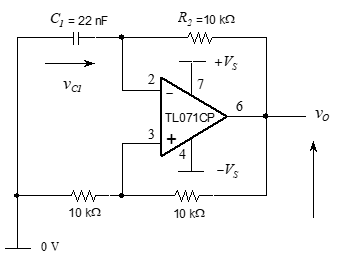
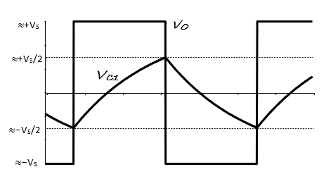
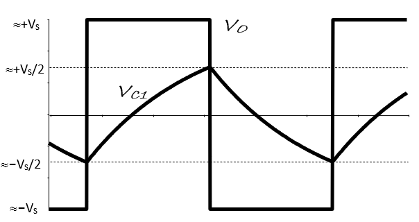
comprises an oscillator circuit. As shown in , the capacitor charges until $v_{c1}$ slightly exceeds $\frac{+V_s}{2}$. Then, $v_o$ switches from +ve saturation at $+V_s$ to -ve saturation at $-V_s$. With $v_o = –V_S$ the capacitor starts discharging. It continues to discharge until $v_{c1}$ falls slightly below $\frac{–V_s}{2}$, at which point $v_o$ switches back to $+V_S$ and the charging phase begins once again. Capacitor charging and dis-charging phases continue indefinitely; the output never settles; it oscillates.
Circuit analysis and operating frequency estimation
Exercise 1a
The generalised form of capacitor voltage response for a first-order circuit is $v_{c1} = K_1 + K_2 e^ {- \frac{t}{RC}}$, which applies over both half-cycles of the oscillator’s output waveform in .
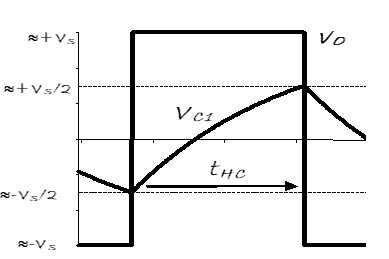
Use this later in your own time with the half-cycle to derive the equation for oscillator half-period below and so the $f_{\text{osc}}$ frequency. In this, assume that the comparator switching thresholds are exactly $\pm \frac{V_s}{2}$ and the comparator output voltage switches between $+V_S$ and $-V_S$. You may also use the op-amp component in the OrCAD/PSPICE analog library to check your results.
Exercise 1b
In a later $v_{c1}$ derivation, what initial voltage should be used at your reference time, i.e. $v_{c1}(0)$ =
Exercise 1c
What should be used for the final steady state voltage that the capacitor charges towards?
Exercise 1d
The $v_{c1}$response equation may be used to show that $t_{\text{half-cycle}} = t_{HC} = R_2C_1 \ln 3$
Exercise 1e
Modify this equation to show how $f_{\text{osc}}$ is related to $R_2$ and $C_1$.
Exercise 1f
Use the $f_{\text{osc}}$ equation to calculate the frequency of oscillation for the circuit values given in .
Oscillator circuit
With the power supply turned off, connect the circuit shown in using a breadboard and components in box CT4a.
Take the power supply outputs first to the 4mm terminal posts on the breadboard, and then connect these to the op-amp using short, tidy links.
Turn on the Agilent power supply and enable its output.
Select +25V to monitor the voltage set on the +25V output and increase the voltage to 15 V.
Press and hold the Tracking key on the power supply, so that the –25V output follows the +25V output setting.
Select –25V to monitor the voltage set on the -25V and check that the voltage is now –15 V. The op-amp should be drawing very little current and not getting hot.
Exercise 2a
With $\pm15 V$ supplies observe the waveforms $v_{c1}$ and $v_o$, making sure that they are correctly aligned on the same graph axes.
Exercise 2b
Using the oscilloscope cursors, measure and record the positive and negative amplitudes of the capacitor and op-amp/comparator voltage waveforms. How close to the supply rails is the op-amp saturating?
\[V_{o(\text{max})} = \qquad V \text{,} \qquad V_{o(\text{min})} = \qquad V \text{,} \qquad V_s - V_{o(\text{max})} = \qquad V\] \[V_{c(\text{max})} = \qquad V \text{,} \qquad V_{c(\text{min})} = \qquad V \text{,} \qquad V_s - V_{c(\text{max})} = \qquad V\]Exercise 2c
Record the periods of the positive and negative excursions of the square-wave waveform.
\[T_{+ve} = \qquad S \text{,} \qquad T_{-ve} = \qquad S\]Exercise 2d
Measure the frequency more accurately using the digital multi-meter.
\[f_{\text{osc}} = \qquad Hz\]Exercise 2e
Explain why the actual frequency of the practical oscillator differs from the frequency calculated in Exercise 1. Do not use measurement error, the resistance inductance, capacitance of wires for this part.
Exercise 3a
Measure the output frequency of the oscillator at eight different supply voltage levels.
| Supply voltage (V) | Oscillator Frequency (KHz) |
|---|---|
| $\pm 16$ | |
| $\pm 15$ | |
| $\pm 14$ | |
| $\pm 13$ | |
| $\pm 12$ | |
| $\pm 11$ | |
| $\pm 10$ | |
| $\pm 9$ |
Exercise 3b
Calculate the total percentage change in oscillator frequency as $V_S$ is changed from $\pm 16V$ to $\pm 9V$
Exercise 3c
Exercise 3c Using observations of the practical waveforms, state with a clear justification why the practical oscillator frequency varies as noted above. Do not use measurement error, the resistance inductance, capacitance of wires for this part.
Exercise 4a
How can the oscillator be implemented with an inductor? Size the inductor value required to give the same $f_{\text{osc}}$ if a series resistor of $100\Omega$ is used. Test your design by simulation using the OPAMP in the Cadence/OrCAD Analog library. You will have to set an initial current e.g., 20mA in the inductor to start operation
Reflection on skill and learning
Complete outside the lab if you run out of time in your lab notebook. Comment on your individual attain-ment as suggested below. What percentage of the lab work did you complete? How do you rate your participation as a lab group member?
What level of proficiency do you feel you achieved in assembling the practical oscillator circuit on a bread-board and testing, debugging and making measurement on the circuit. Choose one of the following and add a comment.
- High –very confident assembling and debugging the oscillator circuit and making measurements on the waveforms. Potential applications could be —-?
- Medium – some further practice required but attained reasonable competence in assembling and some understanding of the form of the results and the circuits imperfections. More practise is re-quired in —-?
- Basic – Seemed to take longer than average to successfully build the circuit and record and under-stand the results. Need significantly more practice in —-?
List two or more ways in which attending and completing the lab work has been of value.
List any suggested changes to the lab work that you identified which would facilitate circuit theory learning and acquiring circuit assembly, testing and measuring skills.