Transient Analysis of RC and RL Circuits
Introduction
This CAD (computer aided design) laboratory session is intended to introduce you to the transient analysis capabilities of the OrCAD/PSPICE circuit-simulation software package.
Circuits may be driven from constant, or time varying sources and the initial conditions of inductors and capacitors may be set to any value to simulate all the circuits included in the work-package notes. Exponential equations may be set up and plotted within the graph-display window. This allows the mathematical equations, derived to model the variation of current and voltage in first-order circuits, to be plotted and checked against actual circuit responses.
RC circuit transient response
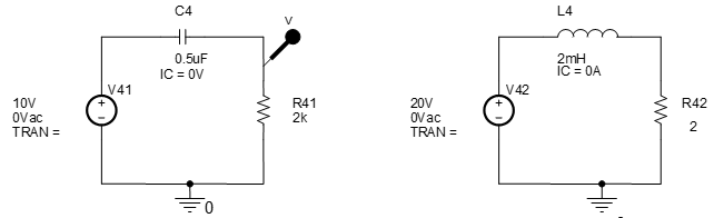
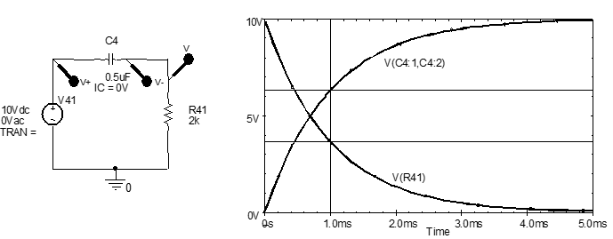
Enter the circuit shown into OrCAD/Capture. Remember to edit component designators and values so that your circuit is the same as .
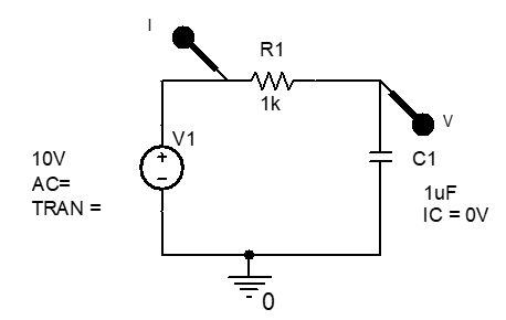
To set the capacitor initial condition, i.e., its initial voltage to zero, click on the capacitor until the whole component is highlighted, not just one of the pins. Then double click on the highlighted component to open its Property Editor spreadsheet.
Click on the cell bellow IC (initial condition) and enter 0V. If you cannot find an IC cell it is likely that you have clicked on a capacitor pin rather than the full component. Hence close the spreadsheet by clicking on the 2nd down top-right x and try again. If you still experience difficulty opening the proper spreadsheet, press the left mouse button and drag the mouse cursor over just the capacitor to highlight it. Select Edit/Properties… from the menu bar and the correct spreadsheet should then definitely be open. Click the top-left Display… button within the Property Editor and select Name and Value, so that the pre-vailing initial condition will be displayed on the schematic.
Close the Property Editor spreadsheet by clicking on the 2nd down top-right x.
Your circuit should be exactly the same as .
Prepare to run PSPICE to simulate circuit operatiion be setting up a simulation profile, i.e., from the menu bar select PSpice/New Simulation Profile, set the Name to trans1, and click Create.
Close the Simulation settings dialogue box by clicking on OK.
From the menu bar select PSpice/Run, or click on the green arrow button on the second from top toolbar, which also starts PSPICE running.
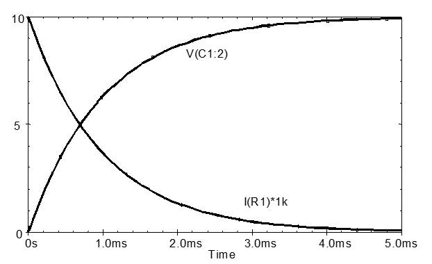
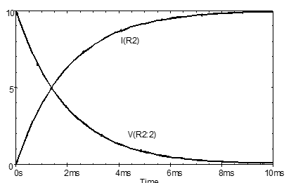
Circuit current is in the order of mA; hence double click on the $I(R1)$ in the graph window and change it to $I(R1) \times 1k$, or $I(R1) \times 1e3$, to multiply it by 1000. Your result should now correspond with .
Time constant measurement
Measure and record the circuit time-constant from the transient response waveforms using both of the procedures given below as option 1 and option 2.
\[\begin{equation} i = \frac{V}{R} e ^{-\frac{t}{RC}} = \frac{V}{R} e ^{-\frac{t}{\tau}} \end{equation}\] \[\begin{equation} v_c = V \left ( 1- e^ {-\frac{t}{RC}} \right ) = V \left ( 1- e^ {-\frac{t}{\tau}} \right ) \end{equation}\]Where $\tau$ is the circuit time constant and $\frac{V}{R}$ are the new steady-state current and capacitor voltage.
When $t = \tau \text{, } e^ {-\frac{t}{\tau}} = e^{-1} \approx 0.368 $
Exercise 1a
To find the time constant from the current waveform, use the graph-window cursors (press cursor button arrow on 2nd from top toolbar in the graph display window) to measure the time when the current is 36.8% of the initial value, i.e., 36.8% of $ \frac{V_S}{R}$ (or initial time-zero value). Evaluate the current and record the measured time constant.
$36.5 \% \text{ of } \frac{V_s}{R} = \qquad mA $
$ \tau = \qquad ms $
Exercise 1b
The output voltage waveform comprises an inverted decay, the time constant can be found by measuring the time when $v_C$ reaches (100-36.8) = 63.2% of the new steady-state value, i.e. $0.632 \times V_S$ Evaluate the voltage and record the measured time constant.
$36.5 \% \text{ of } V_S = \qquad V $
$ \tau = \qquad ms $
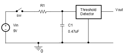
RC-circuits are used with a threshold detector as timing circuits to set a specific time interval. For example, in Fig. 3 when the circuit is first switched on, the RC timing circuit creates a start-up delay to delay or reset the operation of the following circuit, connected after Vout. This is done to ensure the following circuit does not give an unexpected output when the supply voltage is first connected and being established or may be used to reset a digital logic circuit so that it is put into a known state when first energised.
Exercise 2a
If the threshold in voltage is 5V in , calculate the value of the resistance required to give a start-up delay for 3.8s. Start with the charging equation for a capacitor, $v_c = V \left ( 1 - e ^ {- \frac{t}{RC}} \right ) = V \left ( 1 - e ^ {- \frac{t}{\tau}} \right )$ , and solve for $\tau$, then $R_1$.
$ \tau = \qquad ms $
$ R_1 = \qquad \Omega $
Check your value by running a simulation and measuring the time taken for $v_{C1}$ to rise to 5V. The circuit may be simulated without a switch if the initial capacitor voltage is set to zero. The circuit will then behave as if a switch connects $V_{\text{in}}$ and $R_1$ at time 0s.
To set the capacitor initial condition, double click on the capacitor to open its Property Editor spreadsheet.
Click on the cell below IC (initial condition) and enter 0.
Click the top-left Display… button within the Property Editor and select Name and Value, so that the prevailing initial condition will be displayed on the schematic.
Close the Property Editor spreadsheet.
Do this by double clicking the capacitor and set the initial condition, or IC to 0.
RL circuit transient response
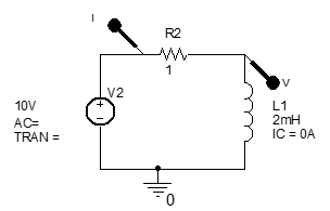
Enter the circuit shown into OrCAD/Capture. You may continue to use the same worksheet if you remove the markers from the first circuit, so that you do not mix up responses for the two circuits.
- Voltage source from SOURCE library as VSRC.
- Resistor and inductor from ANALOG library as R and L.
- Earth symbol, using green-earth right-side-of-screen button, and selecting SOURCE, then selecting 0.
To set the inductor initial condition, double click on the capacitor to open its Property Editor spreadsheet.
Click on the cell below IC (initial condition) and enter 0.
Click the top-left Display… button within the Property Editor and select Name and Value, so that the prevailing initial condition will be displayed on the schematic.
Close the Property Editor spreadsheet.
Your circuit should now be the same as .
Prepare to run PSPICE to simulate circuit operation by editing the simulation profile, i.e., from the menu bar select PSpice/Edit Simulation Profile.
Close the Simulation settings dialogue box by clicking on OK.
From the menu bar select PSpice/Run, or click on the blue arrow on the second from top toolbar, which also starts PSPICE running.
Exercise 3
If the resistance in is increased by a factor of 10, would the ‘charge time’ of the inductor increase or decrease and by how much? Increase the resistor value to $10 \Omega$ and check your answer by simulation.
Predicted change:
Actual change:
Explain why the inductor charge time behaves in the way you found.
Resistor voltage in RC and RL circuits
The circuits in are similar to those in and , which you have simulated, except that the position of the capacitor (or inductor) and resistor have been swapped. Therefore, component currents and voltages will be the same. The only difference will be in the output voltage (assuming we consider the output voltage to be across the far-right component), since it is now taken across the resistor rather than the energy storage element.
Exercise 4
Predict the output (i.e., resistor) voltage waveforms that you expect for the RC and RL circuits in your laboratory notebook. Leave incorrect results for Ex 4 if you later find you were wrong. You will not be marked down if they are wrong. Ex.5 will be marked though and must be right.
Enter the circuits in into OrCAD/Capture.
Re-simulate the first circuit using a voltage-differential marker as well as the ordinary voltage marker to plot the capacitor and resistor voltage responses for the RC circuit shown in
in the same graph window. The voltage differential marker is accessed from the appropriate 2nd from top toolbar button or by selecting using the differential-voltage marker button or PSPICE / Markers / Voltage Differential.
Exercise 6a
What would the resulting waveform look like if the $v_C$ and $v_R$ transient-response waveforms were added together?
Exercise 6b
Sketch a ±10V, 20ms square-wave and superimpose a sketch of the steady-state output-resistor voltage wave-form that would be obtained when this is applied to the input of the RC circuit in .
Exercise 6c
Sketch a ±10V, 20ms square-wave and superimpose a sketch of the steady-state capacitor voltage waveform that would be obtained when this is applied to the input of the RC circuit in .
Generating repetitive waveforms
Square-wave and triangular waveforms may be generated by a number of methods in PSPICE. One of the simplest methods is to use the pulse voltage source.
Open a new simulation project file for the next exercises.
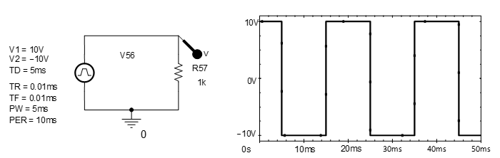
Use a VPULSE voltage source from the SOURCE parts library and enter the circuit shown in .
Edit the circuit values until they are equivalent to those in and simulate circuit operation for 20 ms to get the waveform shown in .
Square-wave waveform generator
Use a VPULSE voltage source from the SOURCE parts library and set up the circuit shown in .
Edit the circuit values until they are equivalent to those in Fig.8 and simulate circuit operation for 50ms or so to get the waveform shown in .
Exercise 7a
Add a capacitor to the circuit and use the RC-circuit with a pulse generator to check that your predicted waveform for Exercise 6b is correct. Redraw the waveform if there is a significant difference. Check especially that the zero-crossing regions of your waveform sketches accurately match the simulation result.
Exercise 7b
Modify the RC-circuit connection and check your waveform prediction for Exercise 6c. Adjust the waveform pulse-width and period if necessary. Check especially that the voltage amplitudes of your waveform sketch accurately match the simulation results.
Exercise 7c
What is unusual about the voltage amplitude obtained in Exercise 6c and 7b and how do you ex-plain their value?
Reflection on skills and learning
Complete outside the lab if you run out of time in your lab notebook. Comment on your individual attainment as suggested below.
What percentage of the lab work did you complete? How do you rate your participation as a lab group member?
What level of proficiency do you feel you achieved setting up, simulating, and making measurements on the transient responses of 1st-order RC and RL circuits. Choose one of the following and add a comment.
- High –now confident performing transient response circuit simulation and measurement. Can envis-age applying in —-?
- Medium – some further practice required but have reasonable understanding of setting up and running simulations and understand the form of results. More practise in required in —–?
- Basic – can follow the process and results but need significantly greater individual practice ins circuit simulation set up and interpretation of results, especially in —–?
List two or more ways in which attending and completing the lab work has been of value.
List any suggested changes to the lab work that you identified which would facilitate circuit theory learning and acquiring circuit simulation skills.