Testing Op-Amp Circuits on a Breadboard
Introduction
This exercise introduces you to connecting circuits on a breadboard and making a working op-amp circuit. Alternatively, if you are off campus set up the circuits as circuit simulations and make the required measurements on the simulated circuit output.
Equipment
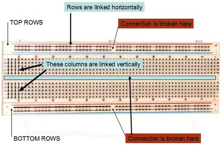
Examine the breadboard that you have and identify which connections are joined horizontally and which are joined vertically. Use the diagram below to help you.
Resitor values
Exercise 1
Use the breadboard to connect the $22k \Omega $ and $10k\Omega$ resistors in series and parallel.
Use the digital multimeter (DMM) and the leads that are terminated with small insulated red and black gripper terminals (not crocodile clips) to quickly measure the values of $R_{\text{series}}$ and $R_{\text{parallel}}$ very precisely. Record the values to four significant figures.
\[\begin{align*} R_{\text{series}} &= \qquad \Omega \\ R_{\text{parallel}} &= \qquad \Omega \end{align*}\]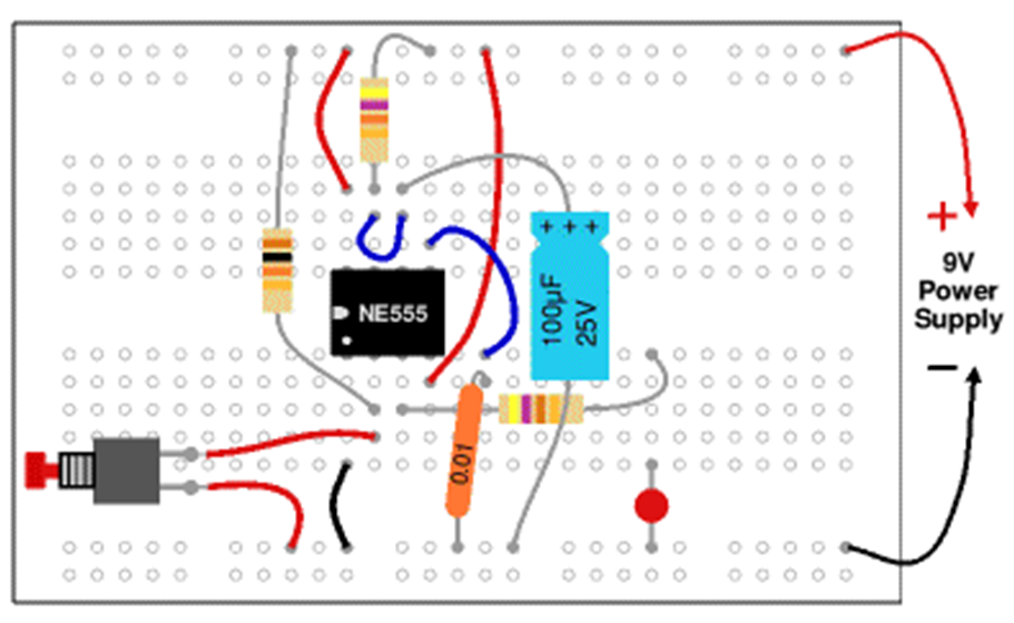
Op-amp power supplies
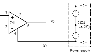
With the power-supply switched off, connect the 0V/COM and the +ve and –ve power-supply output 4mm terminal posts to the 4mm terminal posts on the breadboard using the leads terminated by 4mm plugs in the cable boxes.
Connect the red of one twin lead with 4mm plugs to the +25V power supply output terminal and the black of the same lead to the -25V power supply terminal. Red and black posts on the breadboard should be matched with red and black power supply terminals.
Double up the 4mm plugs on another twin lead to make a single wire lead and connect to 0V/COM connection on the power supply to a separate post on the breadboard, for example green. Connect the waveform generator output to a separate, unused 4mm post on the breadboard to connect a sine wave signal to the amplifier configuration. Then connect the other signal generator black lead plug to the black COM (or 0V) post on the bread-board so that the circuit may be completed as shown in .
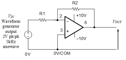
Connect up the bottom of the breadboard posts, $R1 = 10k \Omega and R2 = 22k \Omega$ and the op-amp to form the circuit shown in . In other words, untwist the breadboard terminal posts to expose the inner metal in which there is a hole, and connect to the resistors and op-amp chip pins using wire links of a suitable length. R2 may be connected by inserting its wire leads into the breadboard either side of the op-amp. Connect using very few additional wires.
Turn on the Agilent power supply and enable its output. Select +25V to monitor the voltage set on the +25V output and increase the voltage to 10 V. Press and hold the Tracking key on the power supply for a count of five, so that the –25V output level follows, i.e., tracks, the +25V output setting.
Select –25V to display the voltage set on the -25V and check that the voltage is now –10 V. The op-amp should be drawing very little current and not getting hot.
Set the waveform generator to give a $2V_{pk-pk}$ , 5kHz sine wave output. Connect the two oscilloscope probes – both crocodile clips to 0V and the probes tips to VIN and VOUT by clipping on to a resistor leg (NEVER remove scope-probe tips) – to display the input and output sine waves on the oscilloscope. Turn the oscilloscope on and press Autoscale. If a waveform is not displayed, check the waveform generator output is enabled and that probe crocodile clips are both at 0V and probe tips are connected to the signal.
Inverting Amplifier Measurements
Exercise 2
Using the oscilloscope, measure and record the peak-to-peak values of the input and output sine wave voltages, i.e., $V_{in} and $V_O$.
$ V_{in}(V) \qquad \text{measured}$
$ V_{O}(V) \qquad \text{measured}$
Calculate the amplifier gain using these measure values. $A_{VM}=$
Will this gain value remain constant as signal amplitude is increased or decreased?
Non-inverting amplifier measurements
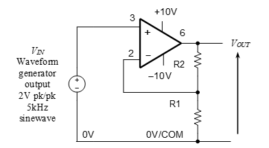
Switch off the power supply output and signal generator output. Keep the op-amp power supply and signal generator connections to 4mm posts in place, but now connect up the non-inverting amplifier configuration shown in with $R1 = 10k\Omega$ and $R2 = 22k\Omega$ nominal values. Repeat the measurements as in the following exercises.
Exercise 3
Using the oscilloscope, measure and record the peak-to-peak values of the input and output sine wave voltages, i.e., $V_{in} and $V_O$.
$ V_{in}(V) \qquad \text{measured}$
$ V_{O}(V) \qquad \text{measured}$
Calculate the amplifier gain using these measure values. $A_{VM}=$
Will this gain value remain constant as signal amplitude is increased or decreased?
Exercise 4
If the voltage levels of the op-amp power supply were decremented from $\pm 10V$ to $\pm 8V$ to $\pm 6V$ to $\pm 4V$, how would the value of gain of your circuit change? Check your expectation by measurement.
Exercise 5
If the signal generator frequency were increased on decreased how would the value of gain of your circuit change? Check your expectation by measurement.
Reflection on skill and learning
Complete in your lab notebook outside the lab if you run out of time. Comment on your individual attainment as suggested below.
What percentage of the lab work did you complete? How do you rate your participation as a lab group member?
What level of proficiency do you feel you achieved in assembling a practical circuit on a breadboard, and testing, debugging and making measurements on the circuit. Choose one of the following and add a comment.
- High – now confident in correctly connecting a circuit and activating and making measurements using the lab station power supply and instrumentation. Especially looking forward to applying in —-?
- Medium – some further practice required in the use of a breadboard, the connection of a power supply or the use of lab instrumentation. More practice especially required in —– to apply with new circuits.
- Basic – can follow the assembly, power-supply connection and output measurement process but need greater individual practice in —– to master without the need for close instruction. The main impediment to more confident breadboard and instrumentation use in new circuits and applications is —– ?
List two or more ways in which attending and completing the lab work has been of value.
List any suggested changes to the lab work that you identified which would facilitate circuit theory learning and acquiring prototype circuit assembling and measurement skills.