Generating Fabrication Files
Designing PCBs in OrCAD Version 17.4.
Generating Manufacturing Files
Using OrCAD PCB Editor, you can generate various files that can be manufactured by third party fabrication and manufacturing companies.
These manufacturing files include Gerber files, Excellon NC Drill files, DXF files, IPC2581, ODB++ as well as printer/plotter files. For a full list of possible exports explore the Export menu inside PCB Editor. You will only need to produce certain file types contingent on your needs, such as the creation of a manufacturing drill file, or a manufacturing artwork.
To generate some of these output files, complete the following steps in Allegro Venture PCB Designer Suite:
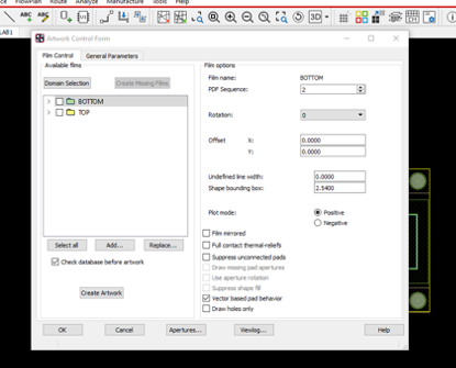
In the General Parameters tab, select Gerber RS274X under Device type as it is the most standard Gerber format used today by most PCB Fabricators.
Maximising these settings guarantees the best quality output data without any rounding issues.
Optional: Set a Prefix and Suffix like jobname- and -Issue1. This way your artwork film names will include the jobname and issue. You can then standardise on a film name (like TOP, BOTTOM, SPTOP, SMTOP) so when your artwork film is generated the film will be called jobname-TOP-Issue1.art.
Accept the remainder of the default settings and click OK to close the Artwork Control form dialog box.
Turn off all layers in Global Visibility in the Visibility tab on the right-hand side.
No further guidance.
You will find this in the Options tab on the right-hand side.
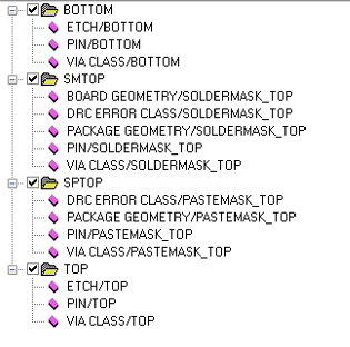
Then click OK to add the new film. Right-click on the ETCH/TOP item and in the Subclass Selection window select Board Geometry > Soldermask_Top. Click OK. Right-click and cut all other subclasses in the Film Control selection window. Repeat this process to add all the subclasses shown in .
Repeat the steps from “Turn off all layers…” to this point to generate new film for: SPTOP. Cut all other subclasses from this list and add the submasks listed in .
Click on the four-square radio buttons for each of the classes: BOTTOM, TOP, SMTOP, and SPTOP. Click on Create Artwork. A message box appears showing the progress of the artwork creation, after the artworks are generated the artwork films with an .ART extension are saved.
Left-click > OK to close the Artwork Control Form dialog box.
NC Drill Data
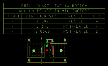
You can now create the Excellon NC drill data. Drill files tell the manufacturers micro-drills where to move to be able create the mounting holes, PCB edges and other design elements. First, add the Drill legend to the PCB.
From the left-hand side menu select Setup > Colours dialog box in the Layers tab, turn the Global visibility on then click OK.
A progress bar will popup that tracks the progress of the drill file creation. Inspect your project folder to see if the XXX.drl file has been created.
Silkscreen
You are now ready to design, simulate and export your own circuits! Congratulations! 🎉
Can I Learn More?
Most definitely. There are a wide range of documentation with OrCAD online and within Cadence. Go to the menu bar of the Cadence Help page and explore some of the Documentation and Web Resources. These include the following helpful guides:
- OrCAD Flow Tutorial (flowtut) - Complete process of capture, simulation and PCB design
- OrCAD Capture User’s Guide (cap_ug)
- PSpice User’s Guide (pspug) - Simulation and analysis information
- The Allegro PCB Editor User Guide (algromast)
- Autorouting with Allegro PCB Editor Tutorial (aleg_spec_tut) – Manual and automatic routing.
- Allegro PCB and Package Physical Layout Command Reference (cmdrefmast)