Components and Arduino
Introduction
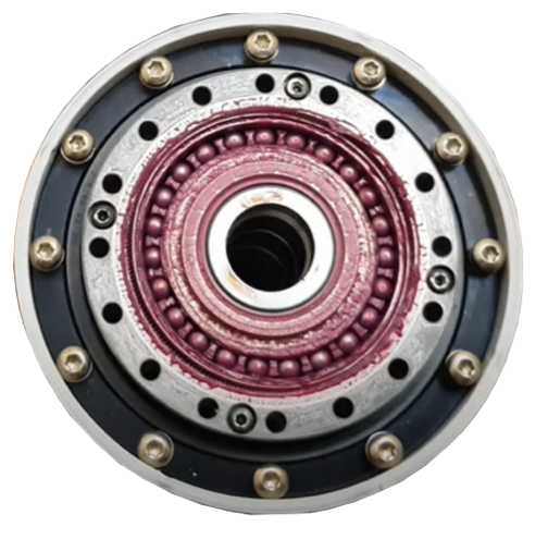
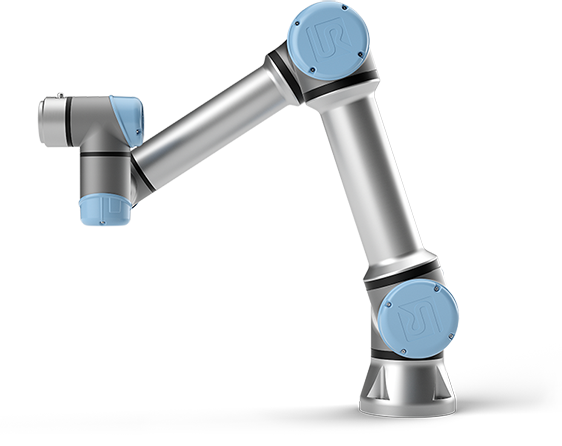
In the second part of the lab, you will program an Arduino board for DC motor position control. Motor control is performed in various industrial applications for CNC machines, 3D printers, robots etc. The motor type for the applications is selected considering various factors such as the project budget, speed, torque, power and size constraints. Especially for robot design, DC motors, stepper motors and servo motors are generally used. The motor output, speed or torque can be adjusted with a gear mechanism. For example, Universal Robots company employs the harmonic drive gear mechanism with servo motors. In this case the robot can provide higher torque and the size of the robot joints can be constrained to the small sizes. , below, shows the direct drive gear mechanism integrated to servo motors of the robot designed by Universal Robot. shows the UR5 robot composed of 6 motors and having 5 kg payload.
Arduino Nano
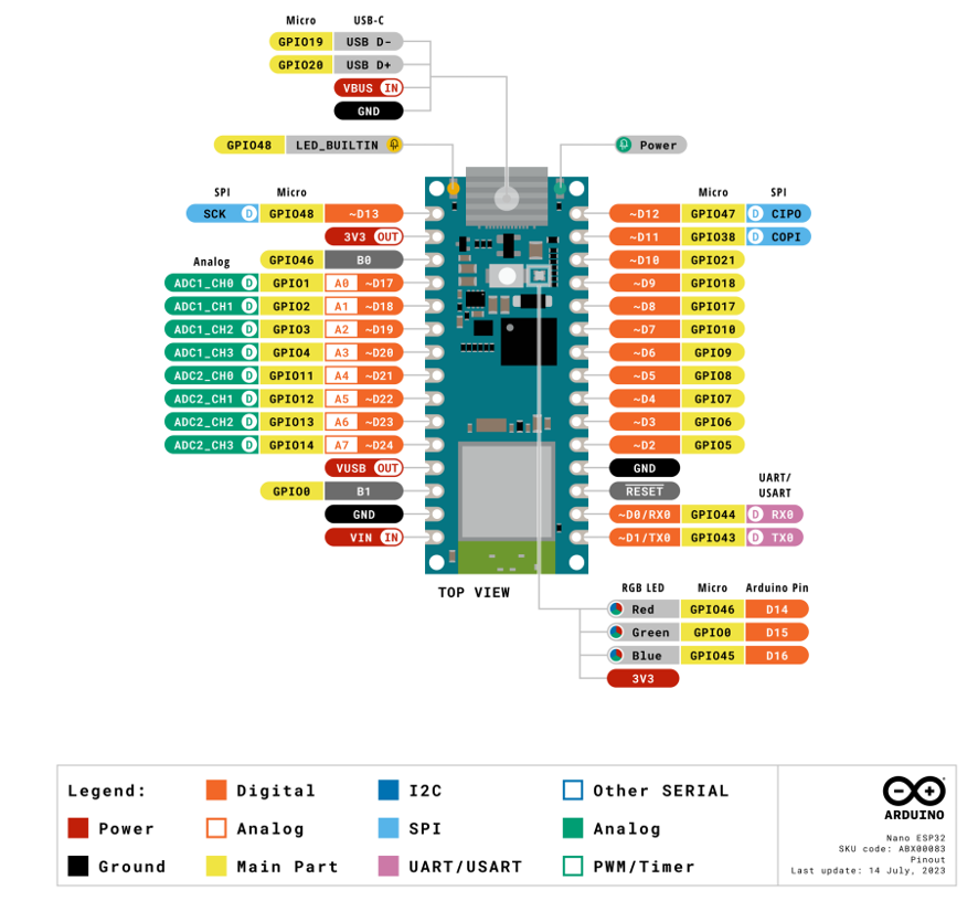
Arduino Nano ESP32 is a Nano form factor board based on the ESP32-S3 (embedded in the NORA-W106-10B from U-blox). The board includes 3 LEDs, a green LED for power, an orange LED for debugging, and a RGB LED for general-purpose use. A single push-button is used for resetting the board. The board can be programmed via the USB-C connector. The same connector also is available for debugging. The specifications of the board are given in the table below:
| Microcontroller | u-blox NORA-W106 (ESP32-S3) | |
|---|---|---|
| USB connector | USB-C | |
| Pins | Built-in LED pins | 13 |
| Built-in RGB LED pins | 14-16 | |
| Digital I/O pins | 14 | |
| Analog input pins | 8 | |
| PWM pins | 5 | |
| External interrupts | All digital pins | |
| Connectivity | Wi-Fi | u-blox NORA-W106 (ESP32-S3) |
| Bluetooth | u-blox NORA-W106 (ESP32-S3) | |
| Communication | UART | 2x |
| I²C | 1x, A4 (SDA), A5 (SCL) | |
| SPI | D11 (COPI), D12 (CIPO), D13 (SCK). Use any GPIO for Chip Select (CS) | |
| Power | I/O Voltage | 3.3 V |
| Input voltage (nominal) | 6-21 V | |
| Source Current per I/O pin | 40 mA | |
| Sink Current per I/O pin | 28 mA | |
| Clock speed | Processor | Up to 240 MHz |
| Memory | ROM | 384 kB |
| SRAM | 512 kB | |
| External Flash | 128 Mbit (16 MB) | |
| Dimensions | 18 x 45 mm |
The pin-out diagram of the Arduino Nano ESP32 board is shown in below:
Arduino Hardware & IDE Familiarization
Open the Arduino IDE software as shown in , where you will write your program.
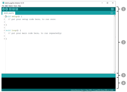
- The Toolbar includes buttons allowing you to upload programs, create, open, and save sketches (Programs written using Arduino Software IDE), and open the serial monitor. From left to right, the buttons perform the following functions:
- Verify: Checks your code if there is any error while compiling the code.
- Upload: Compiles the code and upload it to the Arduino board.
- New File: Creates new sketch (program).
- Open File: Open the sketch from the directory that you want.
- Save File: Saves your sketch (program).
- Serial Monitor: Can be used for debugging tool, monitoring input/output signals.
- Text Editor is for writing your code.
- Message Area gives feedback while exporting and saving the sketches, also displays errors.
- Text Console displays error messages and other information.
Programming - BLINK example
Now, you can test the Blink example from the Arduino.
- Connect your Arduino board to your PC.
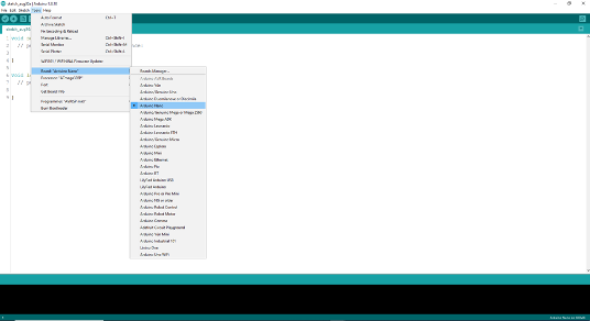
- Select the right core and board. You can do this following the Tools > Board menu, as shown in .
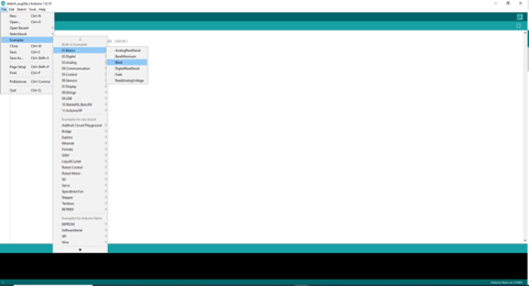
- After you connected your board to a correct Port, you are ready to test the Blink example. Navigate to File > Examples > 01.Basics > Blink, as shown in .
- Upload the sketch (Blink) to your Arduino using upload button. If the upload is successful, you will see the message
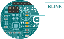
Done Uploadingin the Message Area. - Once the upload is complete, you will see on your board that the LED next to the letter L is blinking. You can play with the blinking speed by changing the delay time inside the delay() function. shows the position of the LED on the physical Arduino board.
Apply the previous knowledge to an external LED - Example
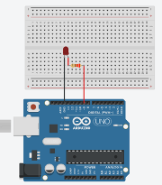
In this activity, you will use Arduino hardware and connect components to Arduino pins. The materials that you will use are Arduino Nano board, a breadboard, a LED and a 330Ω resistor. Connect the cathode leg (-) of the LED to the ground pin (GND) of the Arduino board, and anode (+) leg to the resistor’s leg. Complete the circuit design connecting the other leg of the resistor to the one of the digital IO (Input/Output) pins of the Arduino. The IO pin will provide the DC power that the LED requires. An example of a circuit diagram appropriate for this activity is shown in . Here, pin 9 is used to power the LED.
After you completed the connections of the components for the circuit design, you can program the Arduino to light up the LED. In the setup() function, you need to set the digital pin using the pinMode() function.
The syntax of the pinMode() function is pinMode(pin number, mode); for example: pinMode(9,OUTPUT);.
Your setup() function should appear as follows:
void setup() {
  pinMode(9, OUTPUT);
}Now, you need to set the state of the digital pin to HIGH (1) or LOW (0) with the function digitalWrite().
The syntax of the digitalWrite() function is digitalWrite(pin number, state); for example: digitalWrite(9,HIGH);.
Place this inside a loop() function so that it repeats, as follows:
void loop() {
  digitalWrite(9, HIGH);
}You can upload the code to your Arduino board and observe if the LED light changes. You can observe the status change of the light ON/OFF using the delay function. Moreover, you can monitor the status change of the LED in the Serial Monitor using the serial communication. You need to start the serial communication with the function Serial.begin(speed);. The speed is the transferred data bits per second.
Amend your setup() function as follows:
void setup() {
  pinMode(9, OUTPUT);
  Serial.begin(9600);
}The Serial.println() function helps you to print data on the serial port and debug your code, as demonstrated in .
void loop() {
  Serial.println("ON");
  digitalWrite(9, HIGH);

  delay(1000);

  Serial.println("OFF");
  digitalWrite(9, LOW);

  delay(1000);
}Task A - Potentiometer
Following the previous steps you can now test another example on your own. The example is AnalogReadSerial.
This example can be found similarly to Blink Navigate to File > Examples > 01.Basics > AnalogReadSerial.
The Task is to connect the potentiometer and print the values to screen.
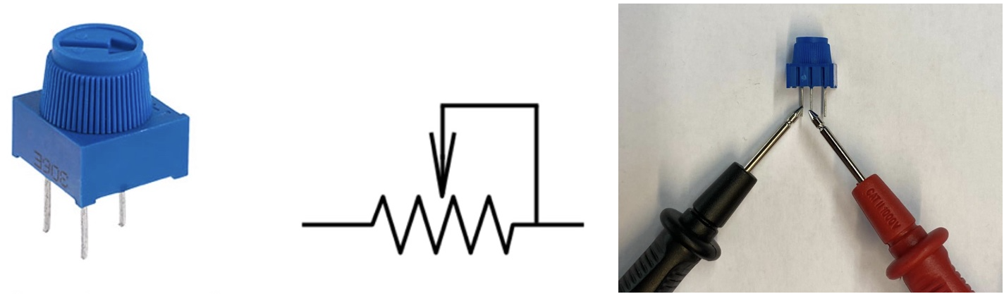
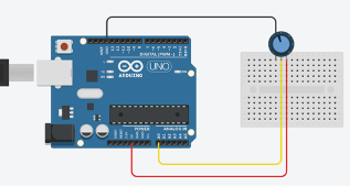
Now, you can use the trimmer with your Arduino board. Connect the first pin of the trimmer to 3.3 volts, and third pin to the ground of the Arduino. The middle pin will be connected to the pin of the Arduino that you would like to read the analog change on Arduino. The circuit should be similar to the one shown in apart for the use of Arduino NANO.
Reflection and exercises on TASK A
Task B
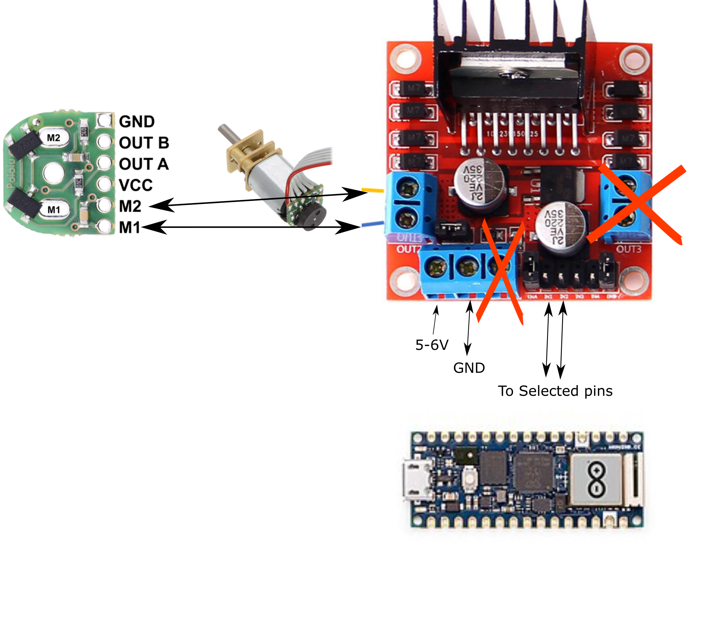
In this task, you will use the trimmer to control the motor states: Halt, forwards and backwards.
The H-bridges requires a min voltage on the logic of 5 V (provide 6 V to the power leaving the jumper wire on). The H-bridge input can be directly driven by the arduino 3.3V output signals.
The DC motor wires are connected to the output pins of the Motor Terminal 1 (OUT1) of the L298 motor driver board. You will need to use a power supply to provide 5 - 6 V to the motor driver pins labelled 12 V (power side) which will power the logic if you leave the wire jumper on if so DO NOT connect the 5 V logic power.
The ground cable from the power supply will be connected to the GND pin of the motor driver board. This same ground must be connected to the GND pin on the Arduino board, such that a common ground is established between Arduino board and motor driver.
You need to wire IN1 & IN2 to two of the GPIO pins of the Arduino board in order to change the motor spinning direction. The state of the motor forward or backward can be controlled using a switch button, a potentiometer or the serial monitor via a PC.