Component Testing and Kit Assembly
Introduction
In the next two hours, you will learn about the various components that constitute a KIT you can assemble to for the motor control coursework element of your portfolio. For each activity please do online searches look for datasheets and understand why you do each step, do not “just” follow along.
Initially you will test each component individually using the laboratory equipment.
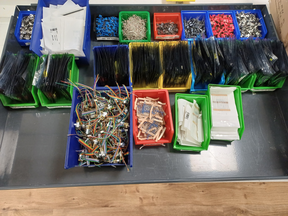
You should all have by now a kit… if not you can find more elements you need on the components tray that should look like this or ask to a technician.
KIT list: You can take the elements a little at a time, there is no rush.
- Kit container (x1)
- Tiny motor+encoder (x1) ONLY ONE
- Servo motor (x1) ONLY ONE
- H Bridge (x1) ONLY ONE
- Breadboard (x1) ONLY ONE
- Male to Male header pins (x1) Each have multiple cables.
- Male to Female DuPont jumper (x1) Each have multiple cables.
- 10K trim pot (x2) you can take up to 4 if needed
- 100uF capacitor (x1) for regulators (you should not need more)
- Red LED (x2) you can take up to 5 if needed
- Yellow LED (x2) you can take up to 5 if needed
- Green LED (x2) you can take up to 5 if needed
- Momentary push switch (x1) you can take up to 3 if needed
- DIP switch (x1) you can take up to 3 if needed
- 330R resistor (x2) you can take up to 10 if needed
- 1K resistor (x2) you can take up to 10 if needed
- 10K resistor (x2) you can take up to 10 if needed
- 5V regulator (x1) (you should not need more)
- 3V3 regulator (x1) (you should not need more)
- Optional LDR (x1) you can take more if needed
- Optional Ultrasonic (x1) ONLY ONE
Individual Component Tests
Exercise - LED & Resistor
A light-emitting diode (LED) is a semiconductor device that emits light when current flows through it. LEDs are used for various applications in automotive industry, medical devices, consumer electronics, traffic lights, etc. You will test an LED with two different resistors, 330 Ω and 1 KΩ.
Connect the cathode (-) of the LED to the negative channel of the power supply, and the anode (+) leg to the resistor’s leg. Connect the other leg of the resistor to the positive channel of the power supply, and set the power supply to 5 V, as shown in .
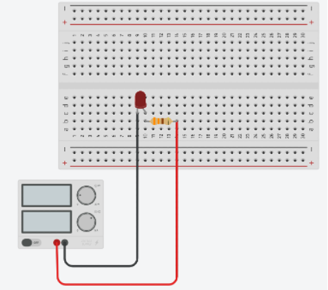
Compare the two circuits and measure the current for each circuit.
Exercise - Trimmer
A trimmer (a.k.a. potentiometer) is an electro-mechanical component used to change the electrical resistance in a circuit manually. It can also be used in a voltage divider circuit to create a variable output voltage. Trimmers can used in applications such as volume control on audio equipment, brightness control on displays, motor speed control and tuning for radio and television.
You can rotate the shaft of the potentiometer to change the resistance value. In order to observe the change of the resistance value of the potentiometer, contact the ground probe of the multimeter to one of the side pins of the trimmer, and contact the red probe to the middle pin of the trimmer, as shown in . Then, rotate the shaft and see the change of the resistance value.
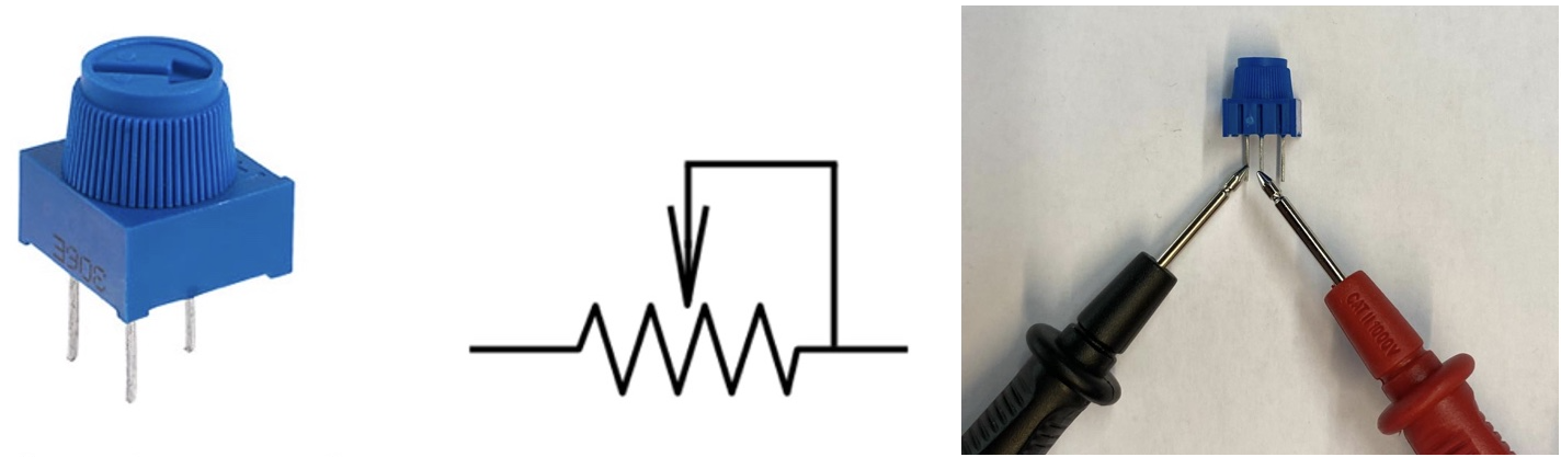
You will design a voltage divider circuit with the trimmer. A simple voltage divider designed with the trimmer is shown in .
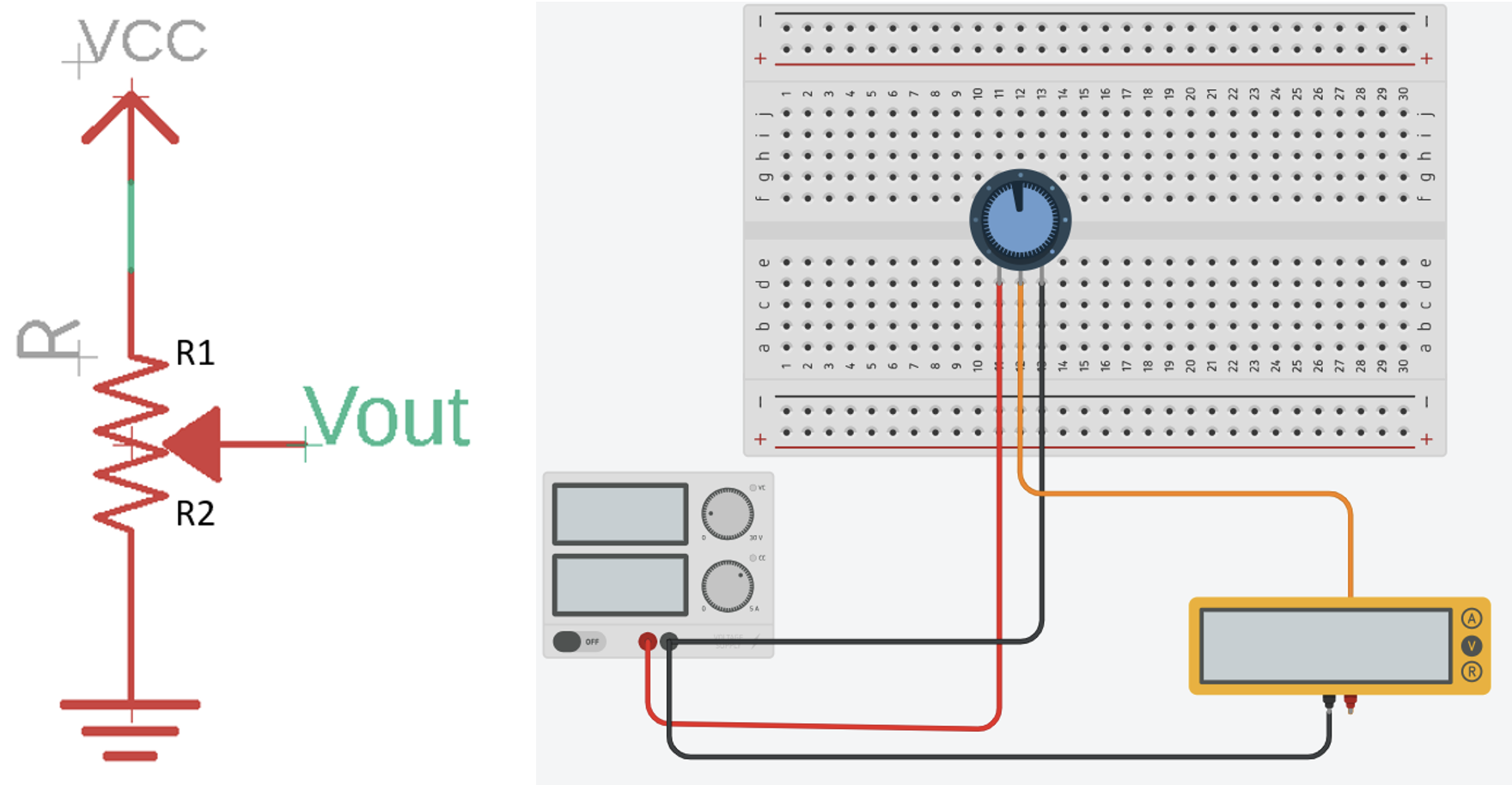
Using the equation below, we can calculate the adjustable voltage output:
\[V_{out} = V_{cc} \times \frac{R_2}{R_1 + R_2}\]Design your voltage divider circuit with the trimmer by connecting the first and third pin of the trimmer to the positive and negative channel of the power supply, respectively. Connect the middle pin of the trimmer to the multimeter, and set the $V_{cc}$ as 5 V to supply the circuit. Rotate the shaft of the trimmer and using the formula and multimeter to observe the voltage output.
Theory - Motor/Encoder
So far nothing relevant would have happened by making a mistake, with the exception of burning the LED or shorting the supply (which you should not do).
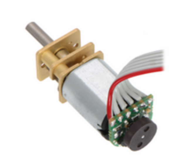
The motor is reasonable sturdy, but it can break and even more delicate is the encoder.
A motor is an electromechanical device that converts electrical energy into mechanical energy. It is a fundamental component in various machines and systems, providing the necessary force and motion for a wide range of applications.
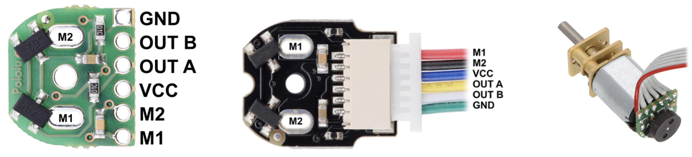
You will test the DC motor composed of a gear box and encoder. Some of the motors include a black coloured encoder board while others include a green coloured board. The pin-outs for each type of encoder, as well as an (green) encoder board mounted on a DC motor are shown in below.
Encoder data can be found here or here.
You will test the encoder and motor in the next following steps.
Exercise - Encoder
Encoders convert mechanical motion into electrical signals or digital data. They are used to measure and provide feedback about the position, speed, and direction of rotation or linear movement of motors. Encoder can be classified based on the sensing technologies; optical, magnetic, capacitive and resistive encoders. The DC motor that you will use has a magnetic encoder pair kit.
The pinout configuration of the encoder board is given below (IGNORE M1 and M2 for the moment):
You will connect the encoder board with 5 V power supply to test the functionality of the motor.
| Pin Name | Description |
|---|---|
| GND | Ground pin. |
| OUT B | Quadrate output B. |
| OUT A | Quadrate output A. |
| VCC | Powers the Hall effect sensors. |
| M1 | Motor Output Terminal |
| M2 | Motor Output Terminal |
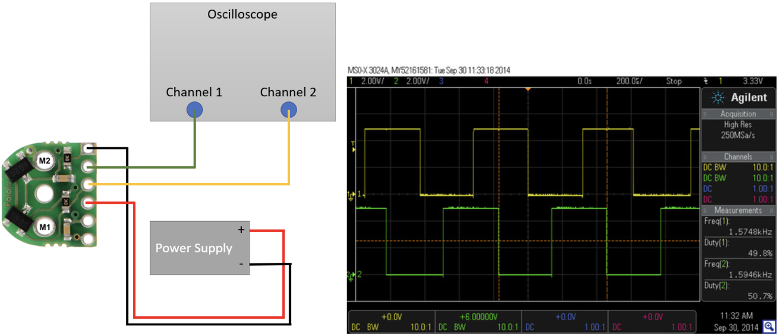
Observe the signal change of the encoder on an oscilloscope. Wire the GND pin of the encoder to negative channel of the power supply, and $V_{CC}$ of the encoder to the positive channel of the power supply, respectively. Then, wire the Output A of the encoder to the Channel 1 of the oscilloscope, and Output B to the Channel 2.
Exercise - Motor Test
The motor is a brushed DC motor. This means that there are no need for fancy signal to drive and power the internal coils. It just requires the right voltage to spin. if you power one terminal and ground the other the current will flow in one direction and the motor will spin. If you swap the connections the current will flow in the opposite direction and the motor will spin the other way.
This particular motor is rated for 5-6 V use 5V.
The access the motor IGNORE all the other connections previously used and focus only on M1 and M2 which connect directly to the motor.
The pinout configuration of the encoder board is given below:
| Pin Name | Description |
|---|---|
| GND | Ground pin. |
| OUT B | Quadrate output B. |
| OUT A | Quadrate output A. |
| VCC | Powers the Hall effect sensors. |
| M1 | Motor Output Terminal |
| M2 | Motor Output Terminal |
I would suggest now to connect the encoder again as in the previous step and observe the encoder signal change on an oscilloscope driven by the motor. ALL GND should be connected. You can also check and log the current requirements at different voltages 1,2,3,4,5V.
Exercise - Motor Controller
The motor is quite small but even if small requires a certain amount of current, even more so bigger motors. Electronic boards do not normally have the capability to directly drive a motor, hence the use of motor controllers or motor drivers.
A motor controller/driver is an element that can receive the control commands from a micro controller (which cannot drive directly a motor), and use this commands to drive power signals (with much higher current specs) to drive the motor.
The motor driver you will use features an L298N chip composed of two standard H-bridges and is capable of driving two DC motors. The motor driver boots the supply voltage from 5 V to 35 V and provides 2 A current per channel (far more than needed). It is shown in below. This controller can also control two motor at the time.
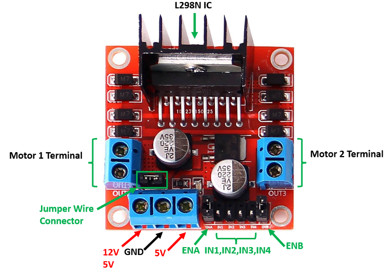
The pinout configuration of the module is as below.
| Pin Name | Description |
|---|---|
| IN1 & IN2 | Motor A input pins used for controlling the motor spinning direction. |
| IN3 & IN4 | Motor B input pins used for controlling the motor spinning direction. |
| ENA | Enables output signals for Motor A (Motor 1 Terminal). Leave the jumper so the output are always enabled. |
| ENB | Enables output signals for Motor B (Motor 2 Terminal). Leave the jumper so the output are always enabled. |
| OUT1 & OUT2 (Motor Terminal 1) | Output pins for Motor A. |
| OUT3 & OUT4 (Motor Terminal 2) | Output pins for Motor B. |
| 12 V | Powers the H bridges of the L298N IC, voltages range between 5V and 12V. Keep the wire jumper and DO NOT use the 5-6 V. |
| 5 V | DO NOT USE - Powers the 5V logic circuitry inside of the L298N IC. This board has a regulator. |
| GND | Common ground pin. |
Exercise - Regulators
You can find the datasheets clicking on the link below:
Datasheet LF33CV 3.3V (or 3V3) regulator
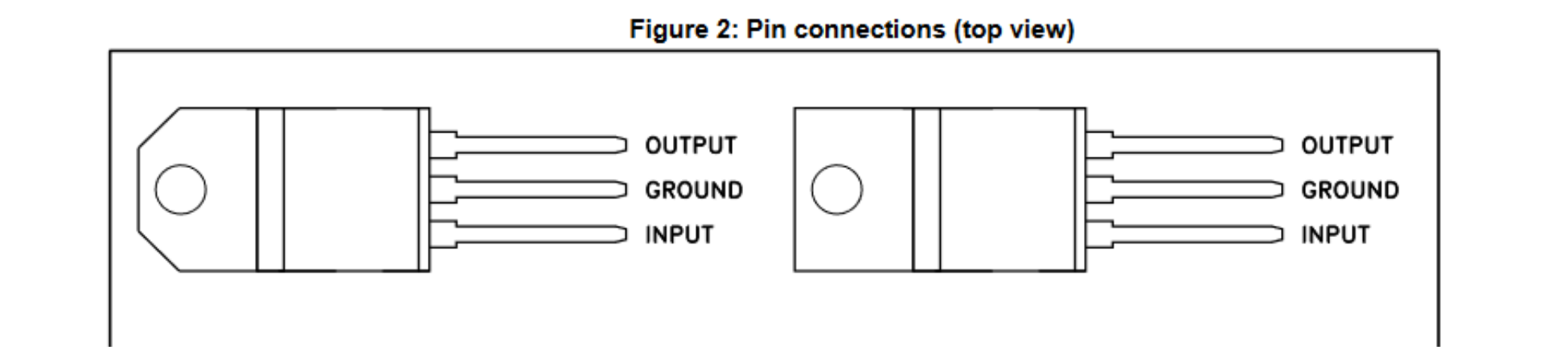
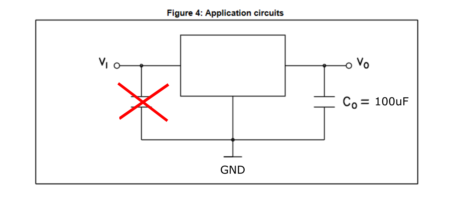
You will test each regulator separately using a breadboard and understand the circuit around them, and their output via the oscilloscope. Reduce and increase the voltage (within the limits) to see how the output changes.
Below the connection circuit from the datasheet, both can be wired in the same way. The Input capacitor is not needed. The output can be anything from 100nF to 100uF. In some cases can be omitted but depending on current requirements the signal can be unstable.