Graphical User Interface (GUI)
Introduction
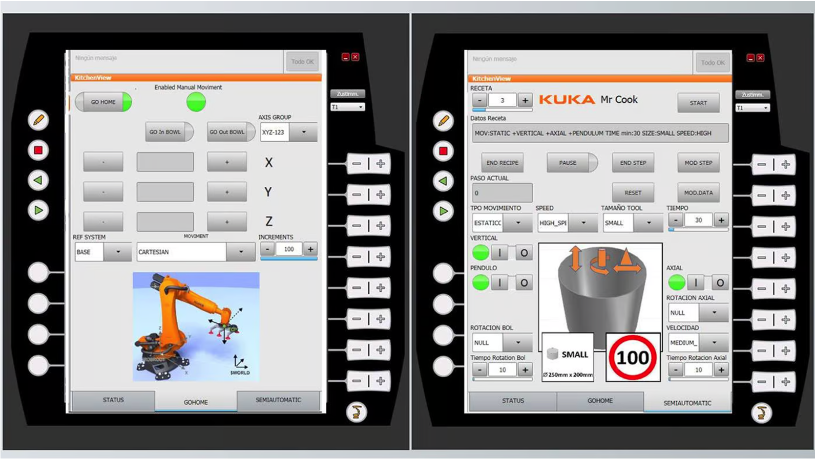
The Graphical User Interface (GUI) is a type of interface that allows users to interact with electronic devices or software through graphical elements such as icons, buttons and menus. GUIs are used in many devices such as smartphones, gaming devices, household appliances and industrial machines. shows a GUI designed to programme the KUKA industrial robots.
In this project, you will develop a GUI on MATLAB that allows the control motors and cameras of the BEATRIX. The project consists of two main tasks: vision and head position control.
First, familiarize with the App Designer which is a graphical development environment in MATLAB, and high-level programming language.
Demonstration of BEATRIX GUI
The video below demonstrates the potential capabilities of a well-built GUI for BEATRIX.
Example Task
This example task is about creating a simple calculator using App Designer tool of MATLAB. You will learn some of the components that you can use for GUI design while completing the calculator example with the provided steps.
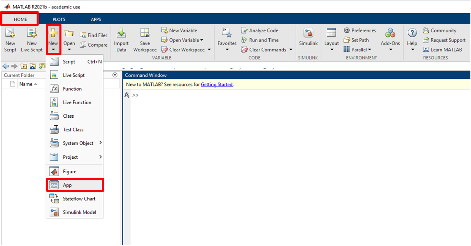
- Open MATLAB software. Then, from the Menubar click Home > New, and Select APP. This will open the App Designer tool of MATLAB, as highlighted in .
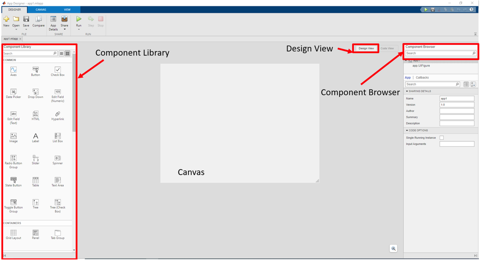
- Now you will see the App Designer Design View, as described by . This environment provides the Component Library that you can use to create interactive features. Any changes you make in Design View are automatically reflected in Code View. This allows you to modify many aspects of your app without writing any code.
You can add a component from the Component Library by two different methods:
- Drag the component into the canvas
- Click a component and then move the mouse cursor inside the canvas and click where you want to put the component
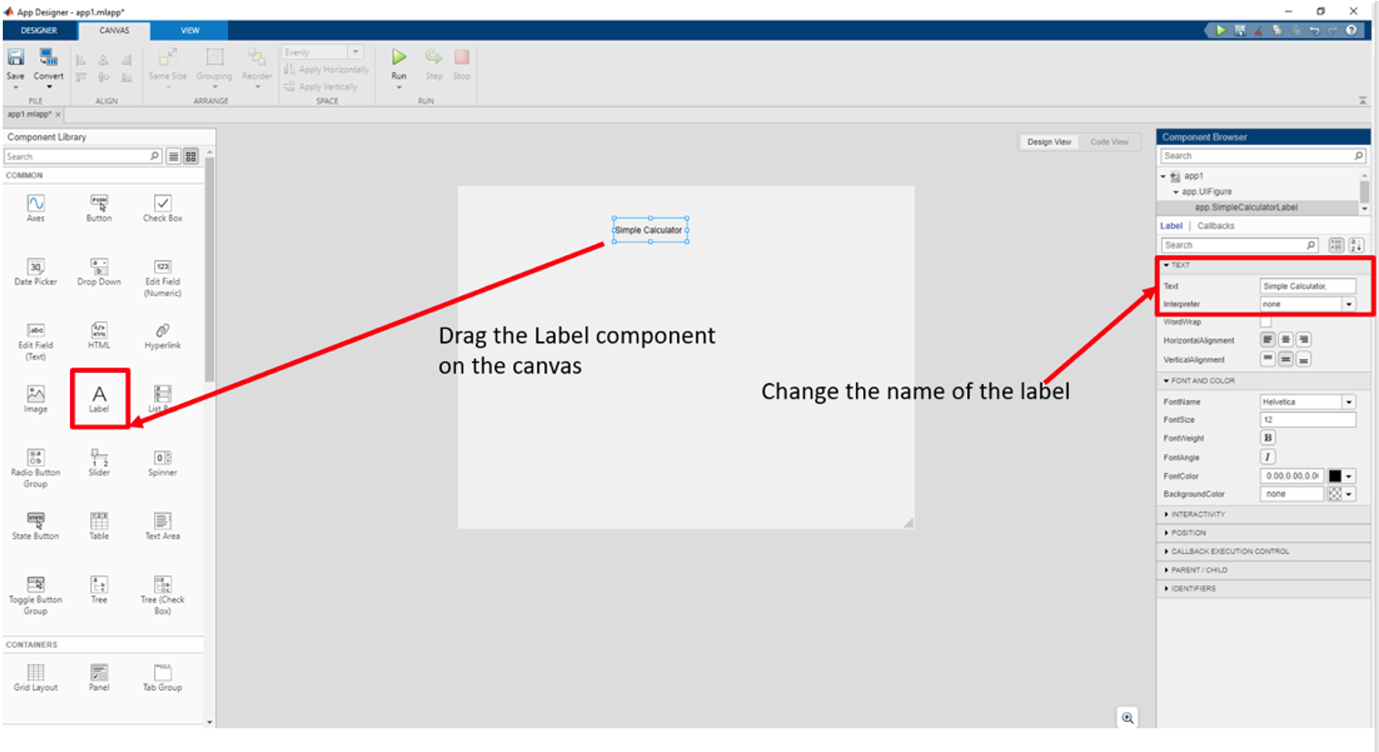
- You can start to create a simple calculator. Drag Label component on the canvas. Change the name of the label to
Simple Calculator. You can customize your component by editing its properties from Component Browser tab, as highlighted by .
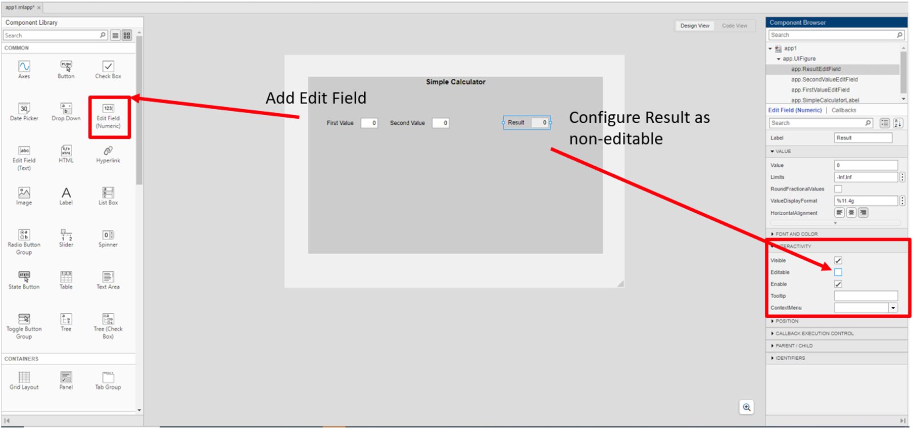
- Then you will add Edit Field (Numeric) to enter the values and show the calculation result. The Result should be non-editable. Click the Edit Field named as Result and untick the Editable placed under Interactivity Feature, as highlighted by .
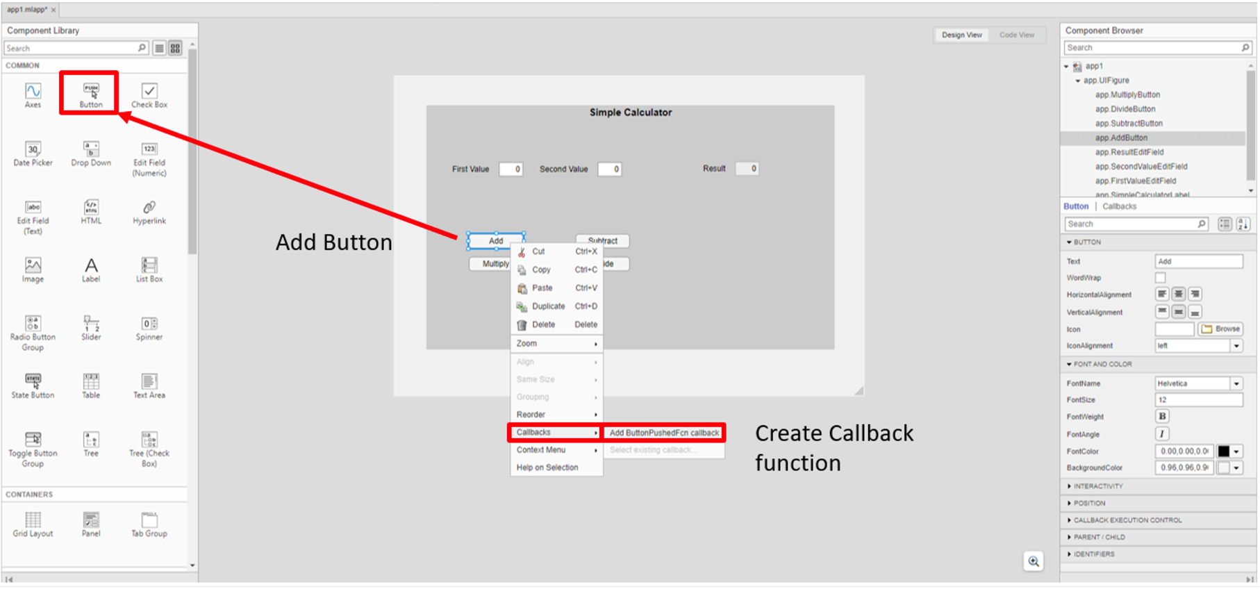
- You will design the calculator operations using the Button component for each mathematical operation. You will use four Button components and name each button Add, Subtract, Multiply and Divide, respectively. After you named the buttons in the canvas, right click on the Add button, then select the Callbacks to create a callback function for this operation. When you push the button Add, Callback function will be executed to perform the action that you specified. The action for Add button will be the sum of the values entered into the Edit Field components. shows this procedure.
- After you created the Callback function for Add component, the software will direct you to Code View where you can program the components placed in the canvas. All Callback functions in App Designer have two arguments:
- app: The app object is required to access User Interface (UI) components in the app as well as other variables stored as properties.
- event: An object that contains specific information about the app user’s interaction with the UI component.
You will enter the numeric values into the Edit field components that you want to use for mathematical operations. The values that you entered should be stored in a variable. In the example code, variable entered through First Value is stored in firstValue.
firstValue = app.FirstValueEditField.ValueThe value property of the FirstValueEditField component is used to access the value entered inside of the component. The same approach is used for the SecondValueEditField component, and the value is stored in variable secondValue. The mathematical operation is defined as:
sum = firstValue+secondValueIn the last step, the result of the addition is displayed in the third Edit Field component named as Result.
App.ResultEditField.Value = sum 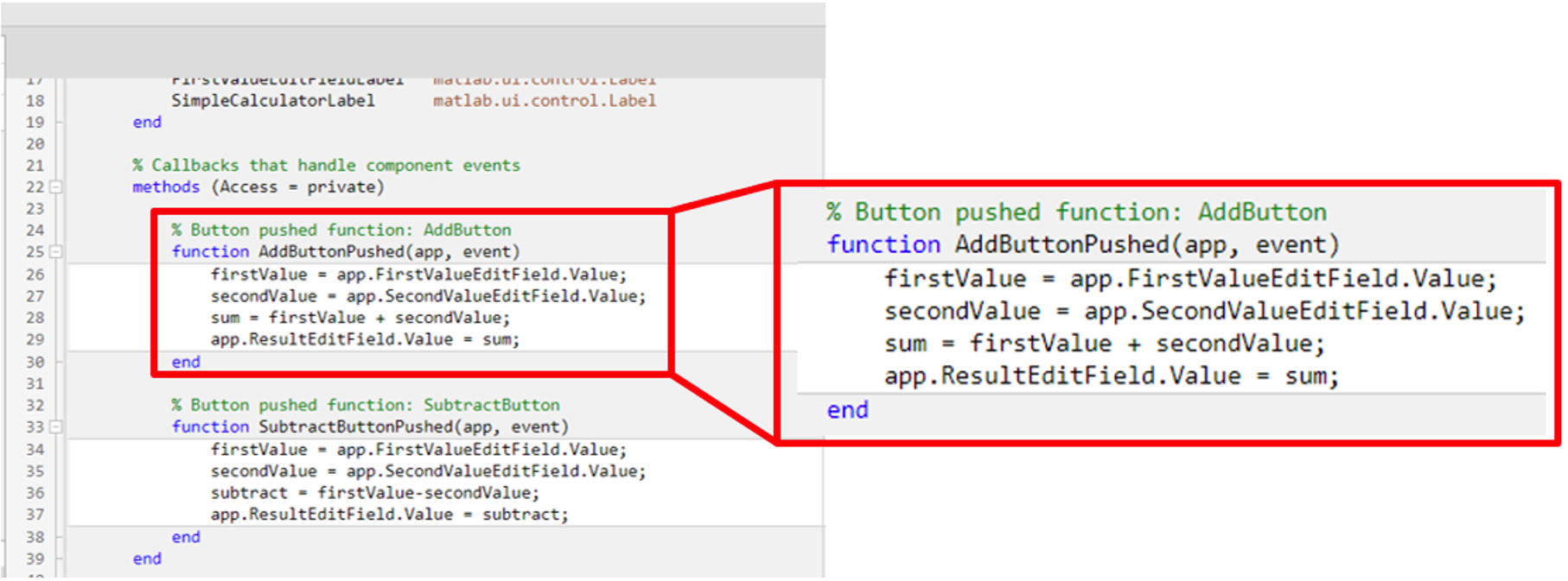
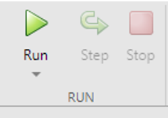
- Now, you can run the program by clicking the run button shown in under the EDITOR or DESIGNER Menu bar to test the Add function. A window similar to that shown in will appear. Enter a number in First Value and Second Value, then click the Add button, and check the Result.
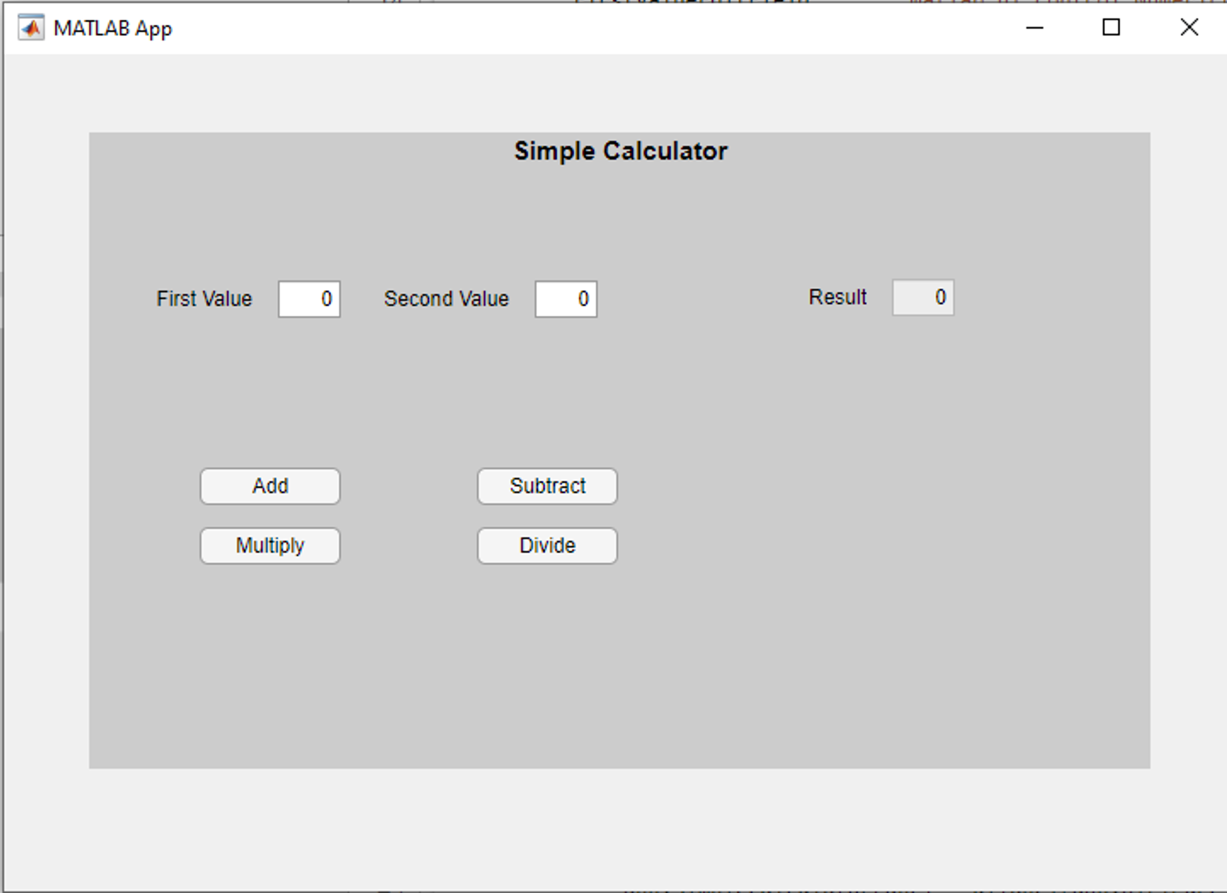
- Create Subtract, Multiply and Divide operations following the steps explained for the Add operation and complete the Simple Calculator.
You can access more information about the App Designer from the MATLAB website.
GUI For BEATRIX
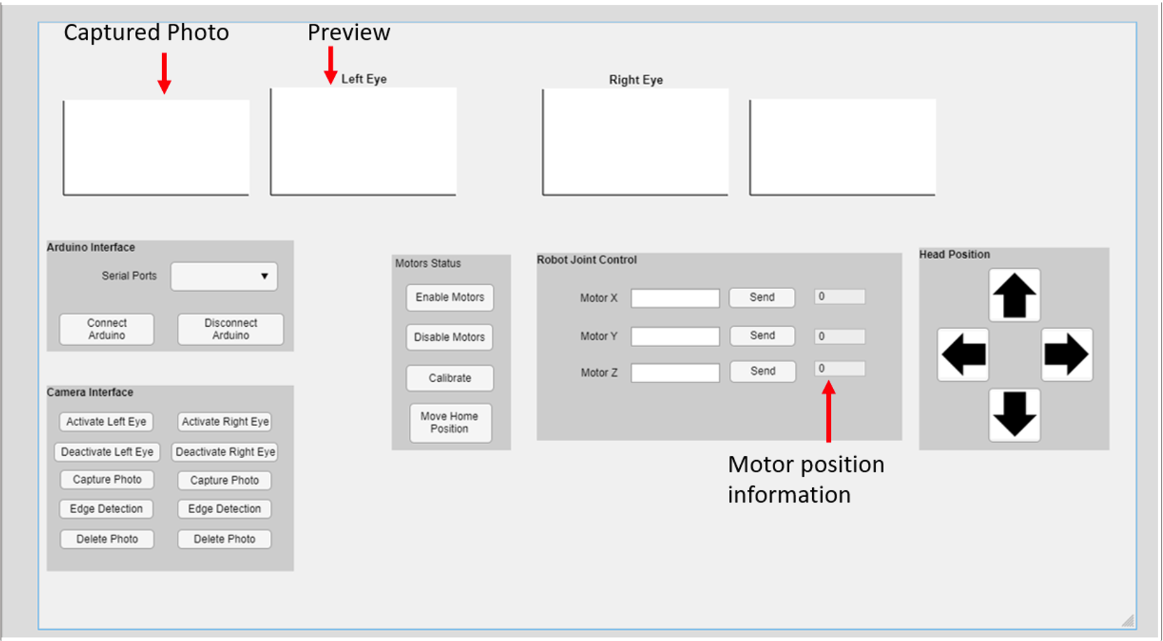
You can start to work on the GUI task of BEATRIX. There are three subtasks divided according to the level of difficulty in this project. shows an example of a GUI design for BEATRIX. You will use all the features shown in .
Establishing Arduino MATLAB Interface (Difficulty: Low)
You can test the robot functions through MATLAB-Arduino interface typing in the Command Window of MATLAB. Create a serialport object using the port and baudrate specified in the Arduino code. The baudrate is 9600 in the Arduino code of BEATRIX. Check which Port your Arduino is connected. You can get help from Arduino IDE, Tools > Port to find the correct port. Let’s assume that the Arduino is connected to port COM5.
ArduinoObj = serialport(“COM5”, 9600)Set the Terminator property to match the terminator that you specified in the Arduino code. “CR” refers to Carriage Return.
configureTerminator(arduinoObj,"CR");Flush the serialport object to remove any old data.
Flush(ArduinoObj);Click here more information about establishing a connection to the Arduino.
You can send data from MATLAB to Arduino using either fprintf or writeline function. You can send formatted strings or combining strings with numeric values using fprintf function. For simple string data, writeline is a convenient choice. You can use writeline to test the robot functions.
writeline(object,data)Use the ArduinoObj for the object of the function, and for data use commands explained in Basic Functionality Testing. Click here for more information on how to send string data.
You can enable motors, calibrate the motor positions, move one of the motors and disable the motors. After you tested these commands with the functions writeline, you can code these in GUI design with MATLAB App Designer.
Tasks
- Connect the Arduino Uno board of the robot to MATLAB for data exchange.
- You can use the dropdown menu to detect the available ports for the serial communication. After you opened the ports under the dropdown menu, you will select the port where your Arduino board is connected.
- Click the Connect Arduino button and establish the connection between Arduino and MATLAB.
- Add a Disconnect Button to remove the connection and the Arduino object generated with Connect Arduino button.
- Activate the motors with a Button component.
- Deactivate the motors with a Button component.
- Calibrate the motors with a Button component.
- Move the robot head to home position with a button component.
- Move each motor defining step values inside of the Edit Field component. Click a Button component and send the defined step values to the Arduino.
- Move the robot head position up, down, left and right controlling the motors together.
Camera Interface (Difficulty: Medium)
In this task you will use two cameras mounted on the eye mechanism of the robot. Find the name of your camera by using the webcamlist function. Make sure that MATLAB can discover your cameras. Type webcamlist function in the Command Window.
webcamlistTo acquire images from the robot’s cameras, you must first create a webcam object. You need to create one object for each camera.
cam = webcamPreview the live video stream from the cameras. Use preview function in the Command Window.
preview(cam)The MATLAB website provides more information about acquiring images from cameras, previewing cameras and setting the properties for image acquisition.
Tasks
- Live stream cameras through Button component or Axes component.
- Deactivate the cameras. Use a background image after you deactivated the cameras.
- Add photo capturing feature to the GUI. Add another Axes component to show the captured photo.
- Add an extra feature such as edge detection to be used on the captured data. You are free to use any feature - you can use MATLAB functions generated for image processing.
- Add Delete button to delete the captured photos.
Improve the Code Modularity, Additional Features (Difficulty: Advanced)
Tasks:
- Add Edit Field text for each motor to monitor their positions.
- Capture photo should work after the cameras activated. Before camera activation, the other camera features should be disabled.
This resource may help you with modular programming.