Equipment
Components of the BEATRIX Robot
The following components are used to design the BEATRIX robot. This page gives you information about the mechanical design of the robot.
Actuator Mechanism
The robot head is moved through three servo motors mounted in ring gear design, as shown in .
In the first step of the assembly of actuator mechanism, three NEMA 17 – 42mm x 40 mm stepper motors are integrated inside a bottom bracket part, as shown in . Then, flange shaft coupling material is mounted to the shaft of each motor to attach spur gear in the next step.
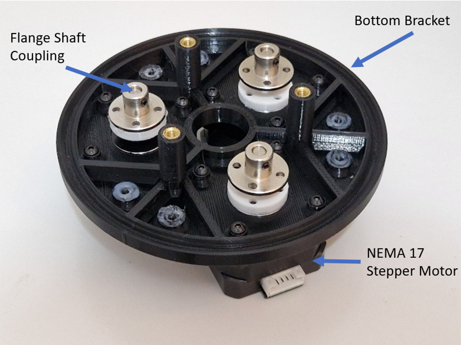
You can find more details about the NEMA 17 stepper motor here.
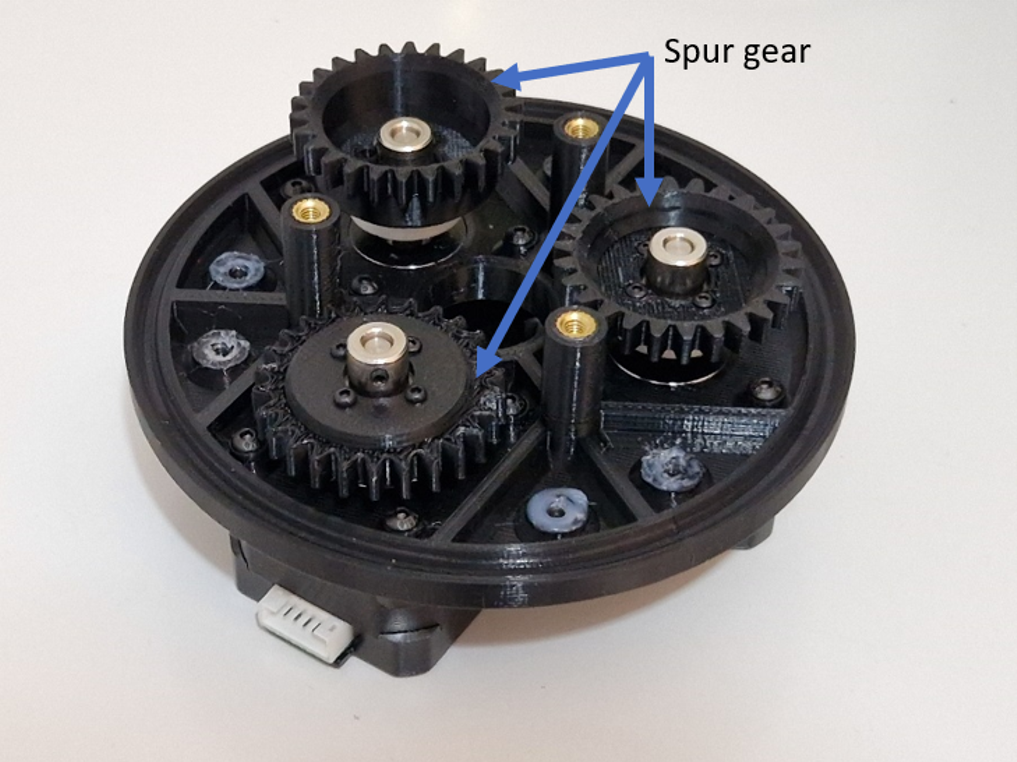
A spur gear is attached to the shaft of each stepper motor, as shown in .
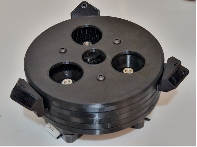
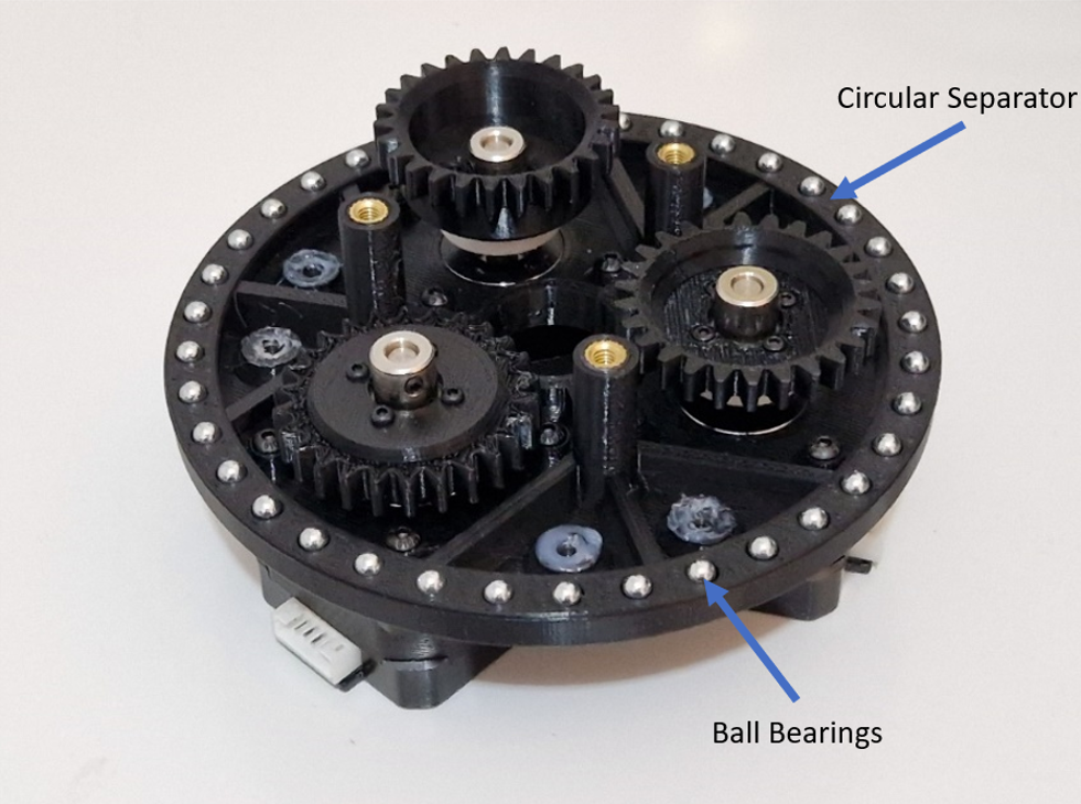
The rotational motion is provided through ball bearings that are placed in a circular separator, as shown in .
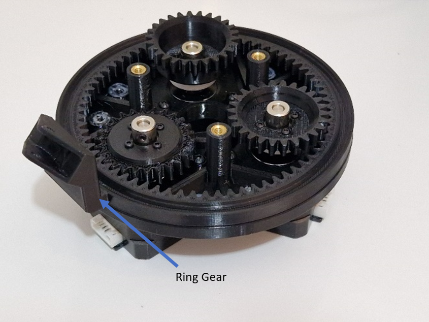
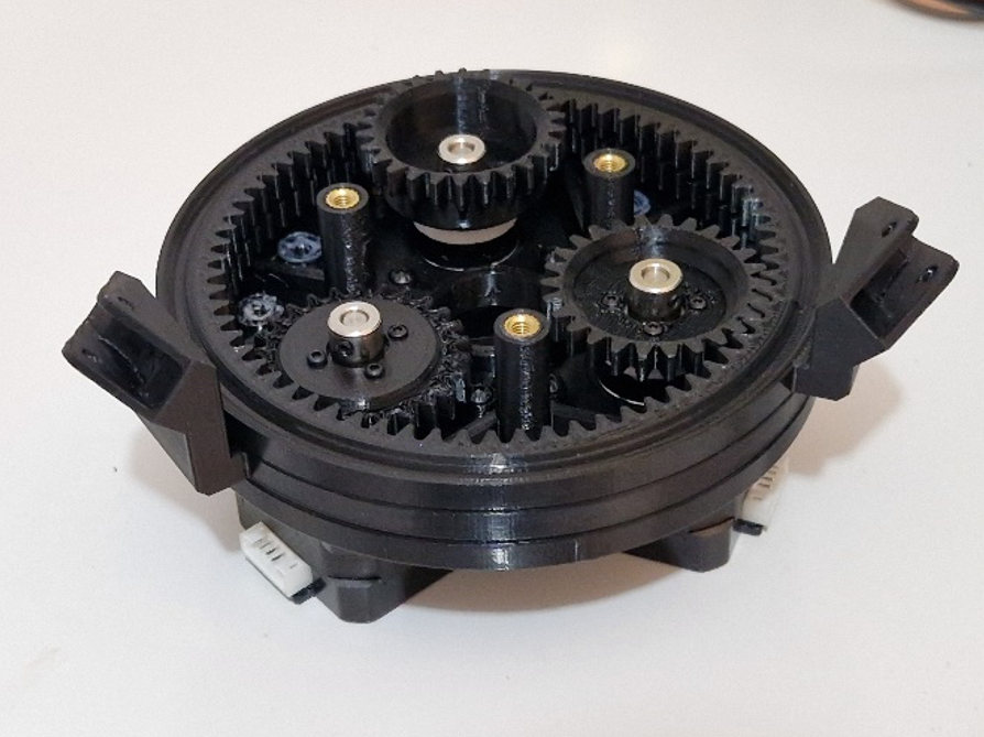
The ring gear is fitted to each spur gear by placing it on the ball bearings, as shown in and .
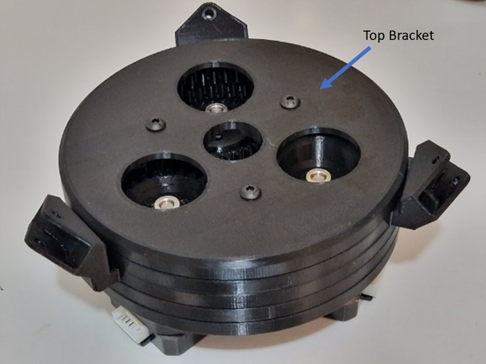
The actuation mechanism is completed by covering the components with a top bracket part, as shown in .
The motor movement is transmitted to the head of the robot through connection rod. The mechanism of BEATRIX is similar to parallel robot configuration, a mobile platform is connected to a fixed base, as described by .
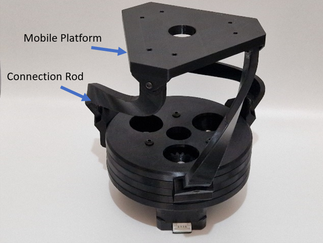
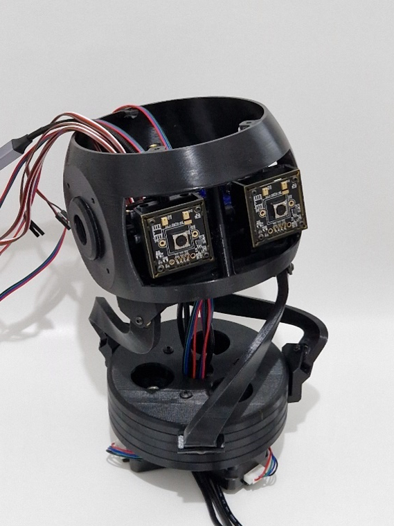
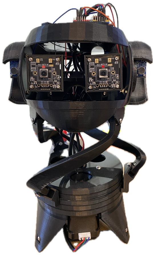
The head of the robot is placed on the mobile platform, and eye mechanism with two cameras is attached inside the head, as shown in .
You can find more details about the USB Camera here.
Microphone
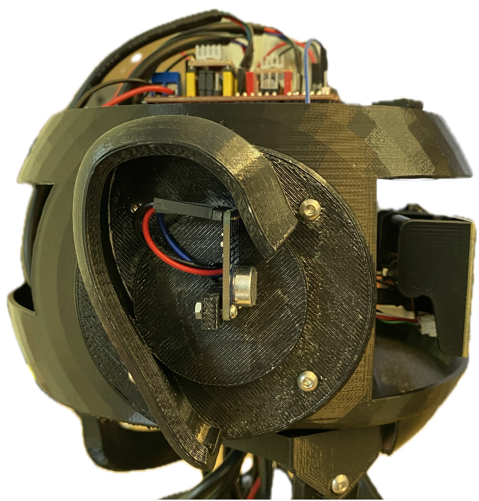
BEATRIX is equipped with two MAX9814 microphones with analog outputs, one of which is shown mounted to BEATRIX’s head in . The sensor is easy to use and is compatible with the Arduino UNO power level (5 volts). The user can get the analog output right away for postprocessing using the Arduino UNO analog pins or connect the microphone to an intermediate ADC to digitize the output and deliver it to the Arduino through an I2C bus.
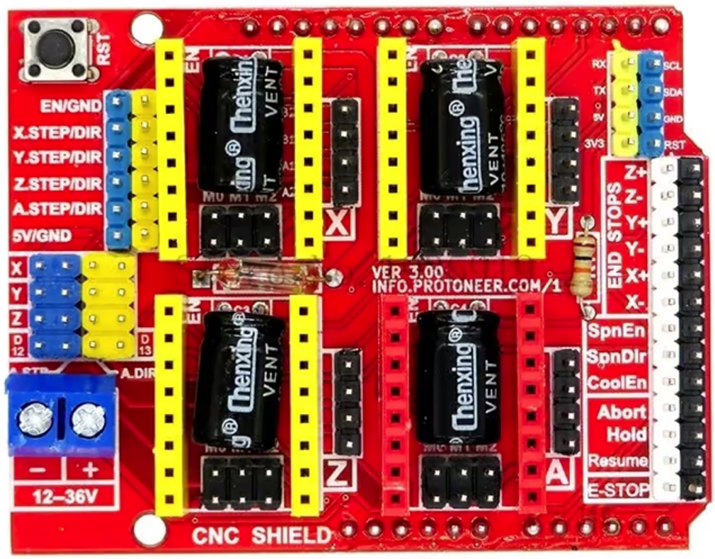
The right ear of the robot is connected to “Hold” pin on CNC shield which corresponds to A1 pin on Arduino, while the left ear of the robot is connected “Abort” pin on CNC shield which corresponds to A0 pin on Arduino.
You can find more details about the MAX9814 microphone here.
Microphone ADC (Optional)
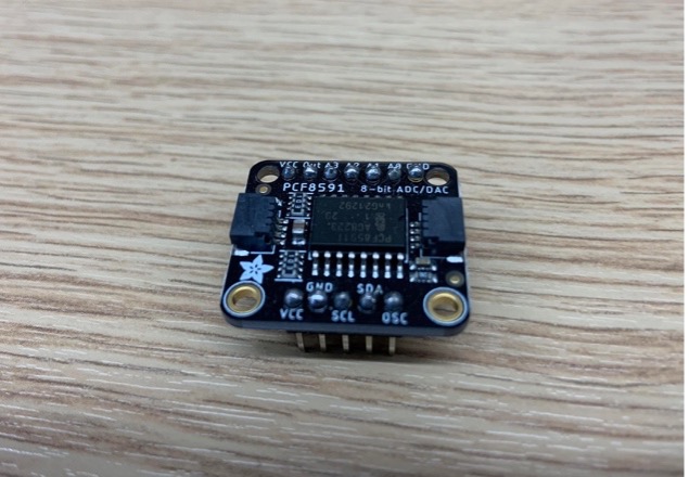
The user can wire the microphone to an intermediate Adafruit PCF8591 Quad 8-bit ADC (shown in ) to digitize the signals coming from multiple microphones and send them all at once to the Arduino via I2C. Up to four microphones can be connected to the ADC module, but in BEATRIX we need only two microphones.
You can find more details about the Adafruit PCF8591 ADC here.
Electronic Components
The head of BEATRIX also includes Arduino UNO where the motor functions are controlled, a CNC shield and motor drivers to drive the motors. shows the completed assembly of the BEATRIX robot.
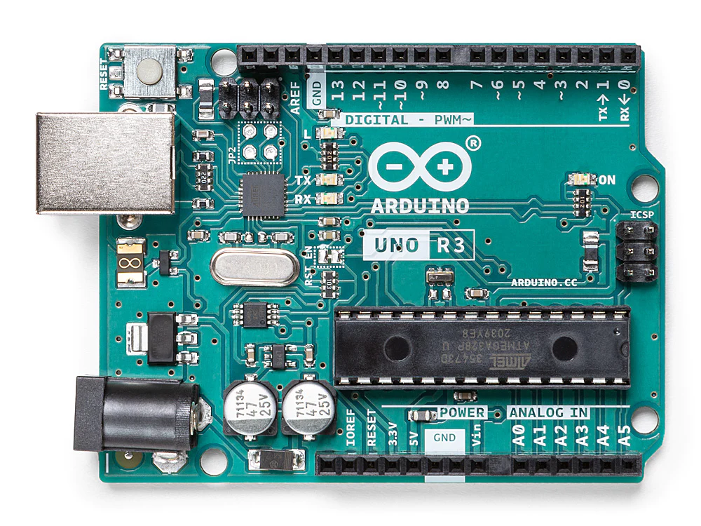
Arduino Uno
It is a microcontroller board based on the ATmega328. It has 14 digital input/output pins (of which 6 can be used as PWM outputs), 6 analog inputs, a 16 MHz ceramic resonator (CSTCE16M0V53-R0), a USB connection, a power jack, an ICSP header and a reset button. It contains everything needed to support the microcontroller; simply connect it to a computer with a USB cable or power it with a AC-to-DC adapter or battery to get started.
You can find more details about the Arduino Uno here.
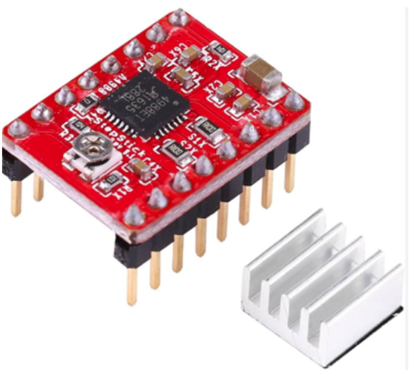
A4988 Motor Driver Module
The A4988 is designed to drive bipolar stepper motors in various applications; from 3D printers to CNC machines and robotics projects.
You can find more details about the A4988 Motor Driver here.
CNC Shield
Arduino-compatible CNC shield simplifies the process of building and controlling a CNC (Computer Numerical Control) machine by providing a standardized interface for connecting and controlling the various components involved in CNC operation. The CNC shield which is used for the BEATRIX has four slots for plugging in stepper motor driver modules. Three slots of CNC shield are used for the stepper motors of the BEATRIX.
You can find more details about the CNC Shield here.