Coursework - Arduino Motor Controller - Tasks
Task A
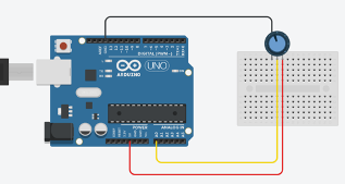
You will change the input signal to the Arduino using the designed circuit with the trimmer on a breadboard, shown in . You will program the Arduino microcontroller to display the received signal voltage values in [V] in the range of 0% to 100% and you will show this change on COM serial monitor using the COM serial communication.
You can rotate the shaft of the potentiometer to change the resistance value. In order to observe the change of the resistance value of the potentiometer, contact the ground probe of the multimeter to one of the side pins of the trimmer, and contact the red probe to the middle pin of the trimmer, as shown in . Then, rotate the shaft and see the change of the resistance value.
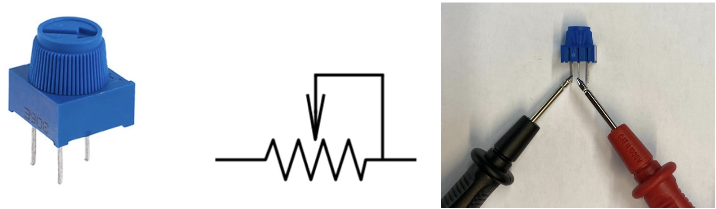
Now, you can use the trimmer with your Arduino board. Connect the first pin of the trimmer to 5 volts, and third pin to the ground of the Arduino. The middle pin will be connected to the pin of the Arduino that you would like to read the analog change on Arduino.
Task B
In this task, you will use the trimmer to control the motor direction: forwards or backwards. The input signal for controlling the spinning direction of the motor can be provided using the serial monitor, the potentiometer or a switch. In order to control the DC motor, you need to connect the H bridge controller with the DC motor.
The motor driver includes L298N chip composed of two standard H-bridges and is capable of driving two DC motors. The motor driver boots the supply voltage from 5 V to 35 V and provides 2 A current per channel. It is shown in below.
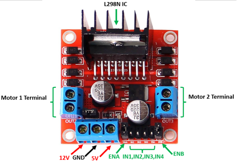
The pinout configuration of the module is as below:
| Pin Name | Description |
|---|---|
| IN1 & IN2 | Motor A input pins used for controlling the motor spinning direction. |
| IN3 & IN4 | Motor B input pins used for controlling the motor spinning direction. |
| ENA | Enables PWM signal for Motor A (Motor 1 Terminal). |
| ENB | Enables PWM signal for Motor B (Motor 2 Terminal). |
| OUT1 & OUT2 (Motor Terminal 1) | Output pins for Motor A. |
| OUT3 & OUT4 (Motor Terminal 2) | Output pins for Motor B. |
| 12 V | Powers the H bridges of the L298N IC, voltages range between 5V and 12V. |
| 5 V | Powers logic circuitry inside of the L298N IC. |
| GND | Common ground pin. |
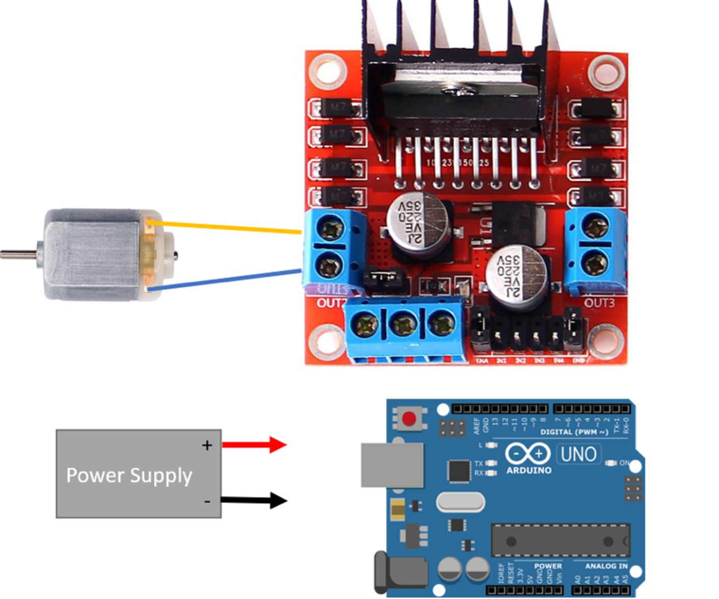
You can start the task with a mini high speed DC motor. Incomplete wiring of the components are given in .
The DC motor wires are connected to the output pins of the Motor Terminal 1 (OUT1) of the L298 motor driver board. You will need to use a power supply to provide 5 V to the motor driver pins labelled 12 V and 5 V. The ground cable from the power supply will be connected to the GND pin of the motor driver board. This same ground must be connected to the GND pin on the Arduino board, such that a common ground is established between Arduino board and motor driver.
You need to wire IN1 & IN2 to two of the GPIO pins of the Arduino board in order to change the motor spinning direction. The state of the motor forward or backward can be controlled using a switch button, a potentiometer or the serial monitor via a PC.
Task C
In Task C, you will use the DC motor composed of gear box and encoder. You will calculate the speed of the motor acquiring the encoder signals, and display the motor speed as RPM and motor states (Halt, Forward, Backward) on the serial monitor.
The encoder board with its pin names and encoder mounted DC motor are shown in below. The red cable is soldered to the GND pin of the motor.
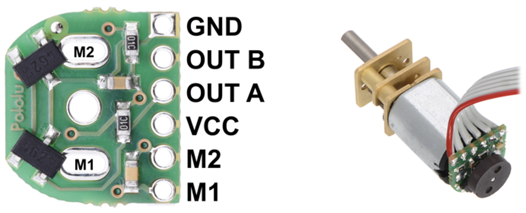
The pinout configuration of the encoder board is as below:
| Pin Name | Description |
|---|---|
| GND | Ground pin. |
| OUT B | Quadrate output B. |
| OUT A | Quadrate output A. |
| VCC | Powers the Hall effect sensors. |
| M1 | Motor Output Terminal |
| M2 | Motor Output Terminal |
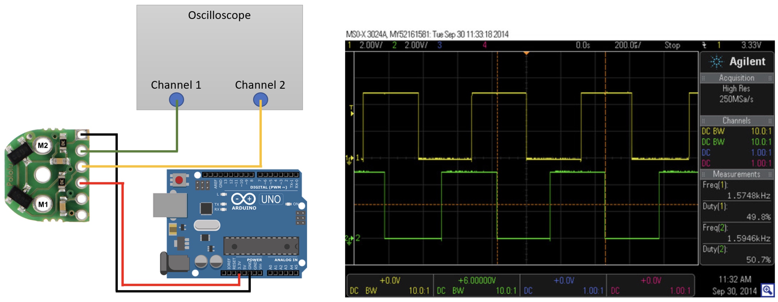
First observe the signal change of the encoder on an oscilloscope. You can use the Arduino board as a power supply for this activity. Wire the GND pin of the encoder to GND pin of the Arduino board, and VCC of the encoder to the 5 V of the Arduino board, respectively. Wire the Output A of the encoder to the Channel 1 of the oscilloscope, and Output B to the Channel 2. When you spin the encoder with your hand, you will see the encoder signals similar to those shown in .
After you test the encoder signals with the oscilloscope, you are ready to use the DC motor with the motor driver. You need to wire M1 and M2 pins of the DC motor to the Motor Terminal 1 pins of the motor driver.
Another important piece of information to calculate the motor speed (RPM) is the gear ratio. To help you calculate this, you can use the motor datasheet here.
This page will help you to receive encoder signals in your program.
Additionally, you will need to use the encoder library. You can check the installed libraries in the Sketch>Include Library menu. If the encoder library is not installed, you can either download it from here and put it in the library directory of the Arduino IDE on the PC that you are working on, or you can search for the encoder library in the Sketch>Manage Libraries menu, and install the library.
Task D
You will modify Task C with the trimmer component to change the motor speed (0% = 0 speed, 100% = maximum speed). You will display the motor speed in RPM, trimmer value and motor state (backward, halt, forward) on the serial monitor. You can use a switch, button or the serial monitor to give direction signal to the motor. You can learn how PWM works by doing the example found here.
Task E
You will improve Task D by implementing PID motor control. You will map the trimmer values to the angle of motor rotation, 0% = -180°, 50% = 0°, 100% = 180°. When you rotate the trimmer, the motor shaft will rotate synchronously, and the motor shaft will settle at the given angle value. You will adjust the overshoot and the steady state of the signal provided by the trimmer by changing the PID constants. You will display the motor speed (RPM), state (backward, halt, forward), PWM and trimmer value on the serial monitor.