Component Testing
Introduction
In this activity, you will learn about and test the components that you will use for the motor control coursework. Initially you will test each component individually using the laboratory equipment. Then you will integrate an Arduino and test the components by integrating them with the Arduino. You can take the required components from the lab in 2E 2.16.
Individual Component Tests
LED & Resistor
A light-emitting diode (LED) is a semiconductor device that emits light when current flows through it. LEDs are used for various applications in automotive industry, medical devices, consumer electronics, traffic lights, etc. You will test an LED with two different resistors, 330 Ω and 1 KΩ.
Connect the cathode (-) of the LED to the negative channel of the power supply, and the anode (+) leg to the resistor’s leg. Connect the other leg of the resistor to the positive channel of the power supply, and set the power supply to 5 V, as shown in .
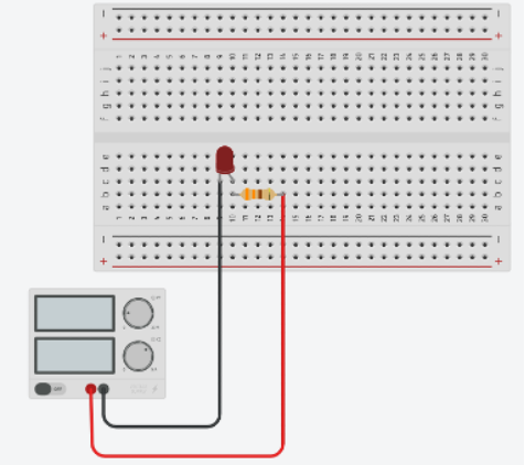
Compare the two circuits and measure the current for each circuit.
Trimmer
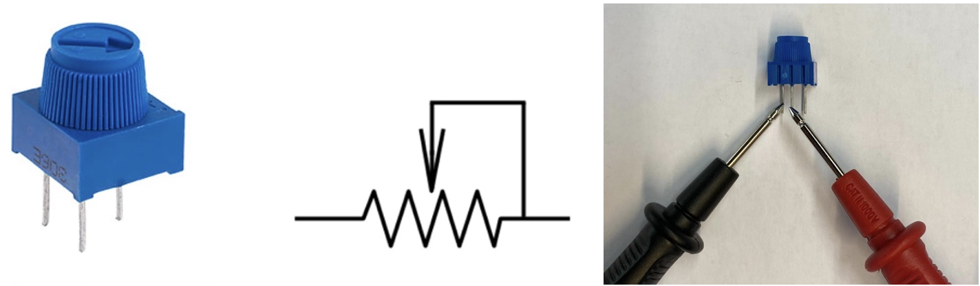
A trimmer (a.k.a. potentiometer) is an electro-mechanical component used to change the electrical resistance in a circuit manually. It can also be used in a voltage divider circuit to create a variable output voltage. Trimmers can used in applications such as volume control on audio equipment, brightness control on displays, motor speed control and tuning for radio and television.
You can rotate the shaft of the potentiometer to change the resistance value. In order to observe the change of the resistance value of the potentiometer, contact the ground probe of the multimeter to one of the side pins of the trimmer, and contact the red probe to the middle pin of the trimmer, as shown in . Then, rotate the shaft and see the change of the resistance value.
You will design a voltage divider circuit with the trimmer. A simple voltage divider designed with the trimmer is shown in .
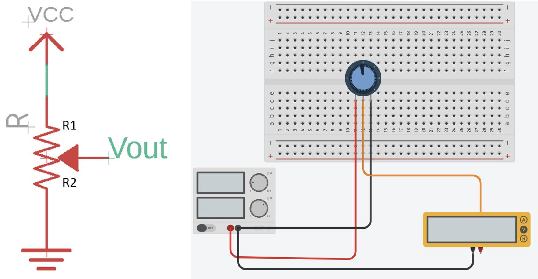
Using the equation below, we can calculate the adjustable voltage output:
\[V_{out} = V_{cc} \times \frac{R_2}{R_1 + R_2}\]Design your voltage divider circuit with the trimmer by connecting the first and third pin of the trimmer to the positive and negative channel of the power supply, respectively. Connect the middle pin of the trimmer to the multimeter, and set the $V_{cc}$ as 5 V to supply the circuit. Rotate the shaft of the trimmer and using the formula and multimeter to observe the voltage output.
Motor
A motor is an electromechanical device that converts electrical energy into mechanical energy. It is a fundamental component in various machines and systems, providing the necessary force and motion for a wide range of applications.
You will test the DC motor composed of a gear box and encoder. Some of the motors include a black coloured encoder board while others include a green coloured board. The pin-outs for each type of encoder, as well as an (green) encoder board mounted on a DC motor are shown in below.
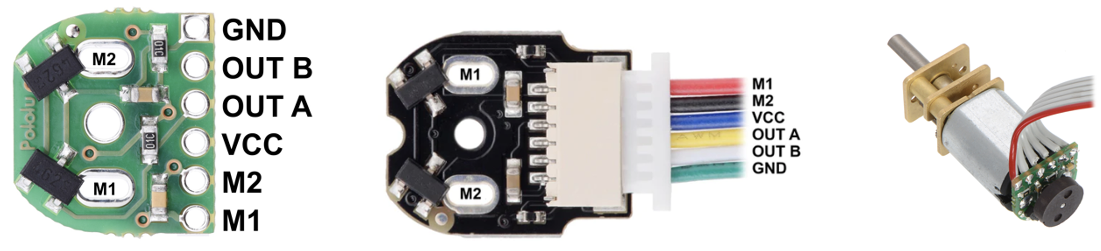
You will connect the encoder board with 5 V power supply to test the functionality of the motor. First, connect the M1 pin of the encoder to the positive channel of the power supply, and M2 pin to the negative channel. Observe the rotation direction of the motor. Then, reverse the motor <-> power supply connections, and observe the behaviour of the motor.
Encoder
Encoders convert mechanical motion into electrical signals or digital data. They are used to measure and provide feedback about the position, speed, and direction of rotation or linear movement of motors. Encoder can be classified based on the sensing technologies; optical, magnetic, capacitive and resistive encoders. The DC motor that you will use has a magnetic encoder pair kit.
The pinout configuration of the encoder board is given below:
| Pin Name | Description |
|---|---|
| GND | Ground pin. |
| OUT B | Quadrate output B. |
| OUT A | Quadrate output A. |
| VCC | Powers the Hall effect sensors. |
| M1 | Motor Output Terminal |
| M2 | Motor Output Terminal |
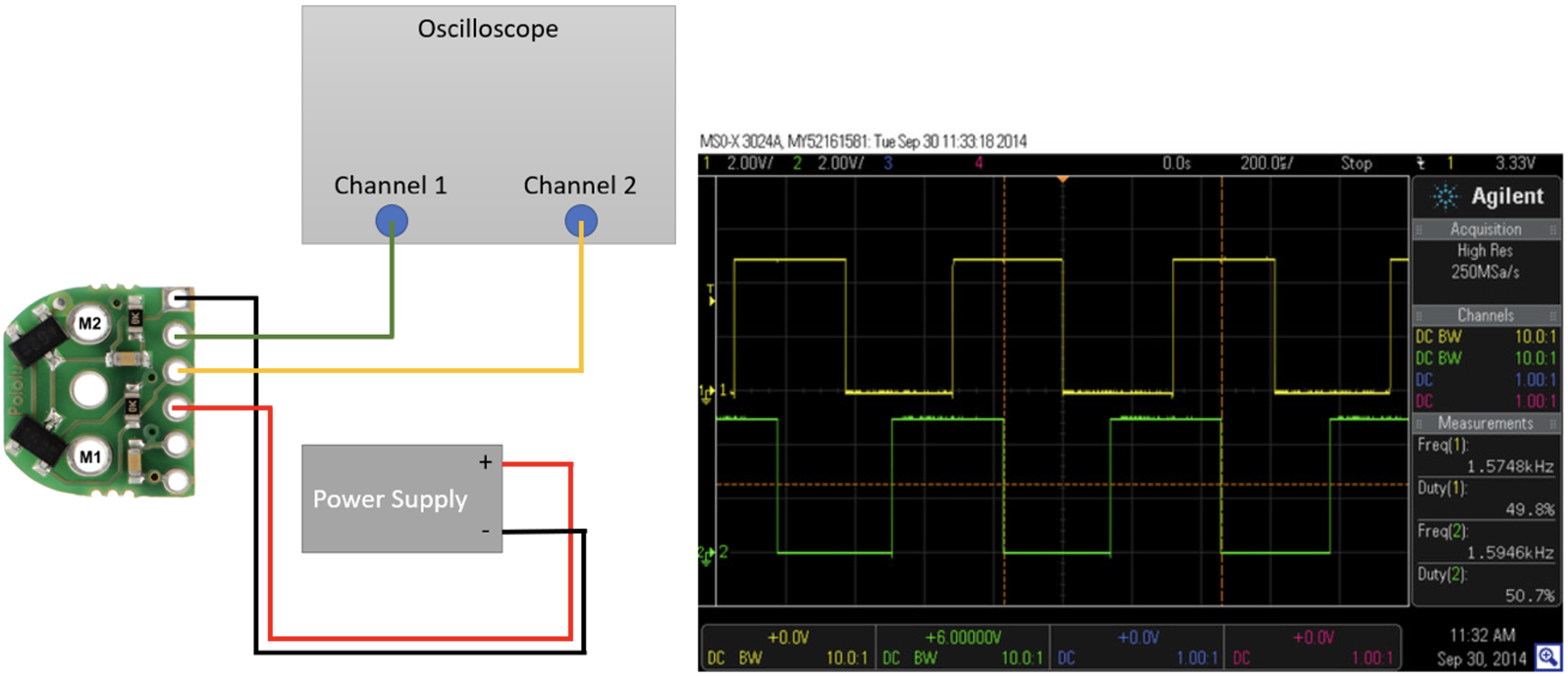
Observe the signal change of the encoder on an oscilloscope. Wire the GND pin of the encoder to negative channel of the power supply, and $V_{CC}$ of the encoder to the positive channel of the power supply, respectively. Then, wire the Output A of the encoder to the Channel 1 of the oscilloscope, and Output B to the Channel 2.
Motor Controller
The motor driver features an L298N chip composed of two standard H-bridges and is capable of driving two DC motors. The motor driver boots the supply voltage from 5 V to 35 V and provides 2 A current per channel. It is shown in below.
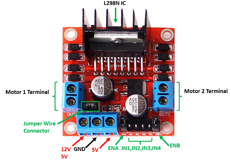
The pinout configuration of the module is as below.
| Pin Name | Description |
|---|---|
| IN1 & IN2 | Motor A input pins used for controlling the motor spinning direction. |
| IN3 & IN4 | Motor B input pins used for controlling the motor spinning direction. |
| ENA | Enables PWM signal for Motor A (Motor 1 Terminal). Also, without enable wire jumpers, PWM signals can be generated. |
| ENB | Enables PWM signal for Motor B (Motor 2 Terminal). Also, without enable wire jumpers, PWM signals can be generated. |
| OUT1 & OUT2 (Motor Terminal 1) | Output pins for Motor A. |
| OUT3 & OUT4 (Motor Terminal 2) | Output pins for Motor B. |
| 12 V | Powers the H bridges of the L298N IC, voltages range between 5V and 12V. Keep the wire jumper to use as 5 V. |
| 5 V | Powers logic circuitry inside of the L298N IC. |
| GND | Common ground pin. |
Arduino Nano
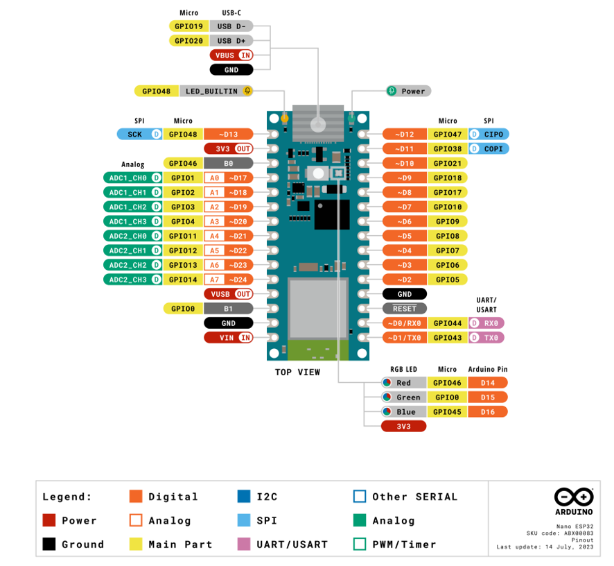
Arduino Nano ESP32 is a Nano form factor board based on the ESP32-S3 (embedded in the NORA-W106-10B from U-blox). The board includes 3 LEDs, a green LED for power, an orange LED for debugging, and a RGB LED for general-purpose use. A single push-button is used for resetting the board. The board can be programmed via the USB-C connector. The same connector also is available for debugging. The specifications of the board are given in the table below:
| Microcontroller | u-blox NORA-W106 (ESP32-S3) | |
|---|---|---|
| USB connector | USB-C | |
| Pins | Built-in LED pins | 13 |
| Built-in RGB LED pins | 14-16 | |
| Digital I/O pins | 14 | |
| Analog input pins | 8 | |
| PWM pins | 5 | |
| External interrupts | All digital pins | |
| Connectivity | Wi-Fi | u-blox NORA-W106 (ESP32-S3) |
| Bluetooth | u-blox NORA-W106 (ESP32-S3) | |
| Communication | UART | 2x |
| I²C | 1x, A4 (SDA), A5 (SCL) | |
| SPI | D11 (COPI), D12 (CIPO), D13 (SCK). Use any GPIO for Chip Select (CS) | |
| Power | I/O Voltage | 3.3 V |
| Input voltage (nominal) | 6-21 V | |
| Source Current per I/O pin | 40 mA | |
| Sink Current per I/O pin | 28 mA | |
| Clock speed | Processor | Up to 240 MHz |
| Memory | ROM | 384 kB |
| SRAM | 512 kB | |
| External Flash | 128 Mbit (16 MB) | |
| Dimensions | 18 x 45 mm |
The pin-out diagram of the Arduino Nano ESP32 board is shown in below: