Coursework - Voltmeter
Objectives
For this coursework task you will design and build the circuitry and software for a simple DC voltmeter, in essence you will create a simplified version of the bench-top multimeters. Using the LCD display and an SPI ADC you will measure DC voltages and display them on the LCD by writing appropriate software. This task combines elements from all of the laboratory sessions so far and enables you to design and build a complete embedded system with multiple interfaces. Your objectives are:
-
Build a circuit using the LCD display module, the ADC, and any switches or resistors that you desire.
-
Import the library code for the LCD and ADC from Moodle and modify them as appropriate, including your own software, for your specific hardware.
-
Measure DC voltages in the range 0 - 5 V with 0.25 V resolution or better.
Hardware
For this activity you are free to use any hardware that is available, however the core functionality is based around the following key components:
-
The PIC16F84A micro-controller
-
The PC1601A LCD display module
-
The MCP3001 10-bit SPI ADC
ADC
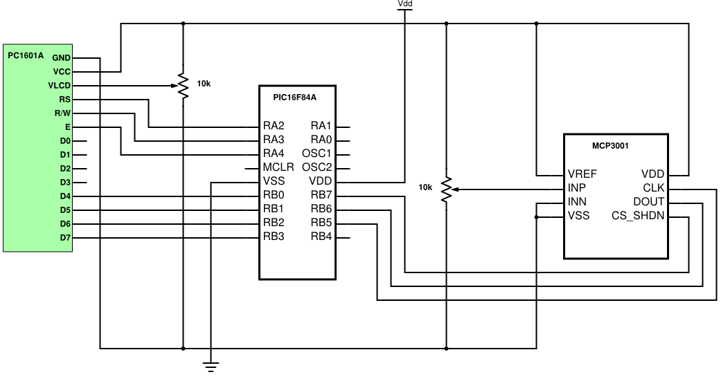
You are already familiar with the design and implementation of the PIC and the LCD display module, you should start with the same circuit you designed for the previous activity. The ADC that you will use is the Microchip MCP3001 (datasheet available on Moodle). The MCP3001 is a 10-bit resolution successive approximation ADC with a three wire SPI interface. The MCP3001 has a differential input (like an op-amp), however for this activity you may prefer to operate it single ended, i.e with INN connected to ground. The MCP3001 is also fitted with a VREF pin that sets the full scale range, allowing you to measure smaller voltages with greater accuracy at the cost of reduced range. A simplified schematic of one possible way to connect the ADC and the LCD to the PIC16F84A is shown in , you may use the other pins for inputs or outputs if you desire.
Hint: The example schematic is not the most efficient in terms of pin usage.
SPI Library
As with the LCD, the software library for the ADC is provided for you and is in the form of two files: adc.h is the header file that you need to include in your code, and adc.c contains the actual functions.
Take some time to read through adc.c and familiarise yourself with the basic functionality of the library. In order to add the library into your project you need to add adc.h to the branch "Header Files" and adc.c to the branch "Source Files", do this by right clicking on the respective branches and selecting "Add Existing Item..." then selecting the correct file. Add the line #include "adc.h" to the start of your main.c file in order to access the ADC library functions, a basic example of the library functions is shown in . You will need to modify adc.h with the pins that your ADC is connected to, as well as the clock frequency of your system.
1
2
3
4
5
6
7
8
9
10
11
12
13
14
15
16
17
18
19
20
21
22
23
24
25
26
27
28
29
30
31
32
33
// CONFIG
#pragma config FOSC = XT
#pragma config WDTE = OFF
#pragma config PWRTE = ON
#pragma config CP = OFF

// Define the oscillator frequency, needed for delays
#define _XTAL_FREQ  4000000

#include <xc.h>
// Include ADC library
#include "adc.h"

// Storage for the raw ADC value
unsigned int voltage = 0;

void main(void) {
    TRISB = 0x00;
    // Set CS high and CLK low for ADC
    CS = 1;
    CLK = 0;

    while(1)
    {
        // Get the current ADC output code as an integer
        voltage = readADC();
        // TODO: Convert integer code into integer voltage, see data sheet
        // TODO: Display voltage on LCD
        // Wait a while
        __delay_ms(200);
    }
    return;
}
The Voltmeter Task
Basic Functionality
The basic hardware for the voltmeter task comprises of an LCD display module and a 10-bit ADC that is connected to the PIC via an SPI interface.
The following describes the basic functionality of the voltmeter:
-
On power-up the LCD should display a welcome message to the user that includes the range of possible input voltages.
-
After a short delay the LCD should display the current DC voltage that is applied to the ADC, with real-time updating. The user may control this voltage from a potentiometer on the board.
-
A hold button may be pressed at any time and will cause the LCD to hold the current voltage measurement.
-
Pressing the hold button a second time will resume continuous measurement mode.
Advanced Functionality
The following advanced functions may be added at your discretion but will attract extra marks as detailed in the assessment weightings in the table below:
-
A second ADC connected to the PIC can measure a secondary DC voltage that is displayed on the LCD, this could also permit differential voltage measurements.
-
Pressing a mode button should enable the maximum voltage observed so far to be displayed alongside the current voltage (peak hold).
-
Pressing a sample button should store the currently displayed voltage in memory.
-
An alarm feature should sound a buzzer or speaker if the measured voltage falls below a pre-defined threshold.
-
The built in timer within the PIC should be used to measure and display the time that the measured voltage spends below a pre-defined threshold.
Marking Framework
This task contributes 25% of your overall unit mark. You will need to demonstrate your working circuit and to upload your C code to Moodle by the deadline. It is important to demonstrate whatever functionality you might have, even if you feel that you have only managed part of the task.
The deadlines for submitting your code on Moodle and for demonstrating it to me are available on Moodle. You will need to book a five-minute slot in advance, a booking system will be made available to you nearer the deadline. Both you and your partner will need to be present for this demonstration.
It is important to meet the submission date to ensure equality amongst students and to enable staff to mark efficiently. The Director of Studies may grant an extension to a submission date should there be valid circumstances affecting your ability to meet the deadline.
If no extension has been granted and a piece of work is submitted after the submission date it will be assessed at a maximum mark of 40%. Any coursework (for which there are no mitigating circumstances or an agreed extension) submitted later than five days after the submission date will normally receive a mark of 0%.
Forms to request an extension are available from the Faculty Student Centre.
Assessment Criteria
Your work will be assessed based on the criteria shown below:
| Assessment Element | Weighting |
|---|---|
| Basic functionality | 50% |
| Advanced functionality | 30% |
| Code quality and formatting | 15% |
| Hardware layout | 5% |
Therefore the maximum mark that you can achieve by solely attempting the basic functionality is 70% (if your code and formatting is perfect!), which is equivalent to being on the 2.1/1st grade boundary.