Activity 1 - Basic C Program
In this activity you will create a simple program to flash an LED, using C instead of Assembly. Your objectives are:
-
Create a C project using the MPLABX software and the XC8 compiler
-
Build a simple PIC circuit
-
Power the PIC from the PICKit3
-
Write and compile a simple C program using the XC8 compiler
-
Control and read individual pins from C
Getting Started
This section shows you how to get started with the MPLAB X Integrated Development Environment.
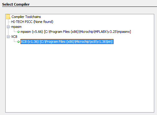
Creating a C based project in MPLABX is very similar to creating an Assembly based project. Create a project in the usual manner, but when asked to select a compiler be sure to select XC8 (not mpasm) as shown in . This will enable the C compiler:
As with the Assembly programs we are going to power the circuit from the PICKit3 programmer, go ahead and configure the power supply using the project properties dialogue as before. The PICKit3 programmer can supply ample current for our designs, if we wanted to run our designs without the PICKit with could connect the PIC to a conventional 5 V regulated power supply.
Turning on an LED
In this first program we are going to recreate the first PIC laboratory and flash a single LED connected to pin RB0. Our objectives are:
-
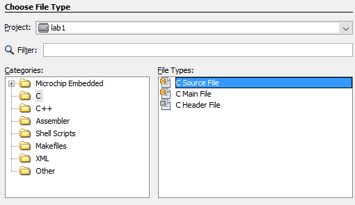
Use MPLABX to create and compile a C program
-
Set the PIC configuration bits using C
-
Setup PORTB as an output port
-
Output some data to PORTB
-
Loop forever in C
Hardware
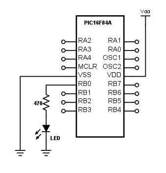
We need to consider how to connect the LED to the PIC. The PIC16F84A is quite a robust chip so it will probably survive a bit of abuse, but we want to do things properly. Limiting the current to < 10 mA through the LED should provide enough light and is within the capabilities of the PIC (see its data sheet). The output voltage of the PIC is around 5 V and there will be a voltage drop across the LED. For this application a 470 $\Omega$ resistor in series with the LED should work fine. Build the circuit shown in .
Software
The software for this basic exercise is provided in the code listing below, you should be able to recognise each line and compare it to the Assembly equivalent. Note that we have made use of the built-in delay functions that provide accurate delays based on the clock frequency we provided. This is significantly easier than performing delays using loops in Assembly.
Once you have written your software you can compile it and (assuming there are no errors) download it to the PIC using the Make and Program Device button within the MPLAB IDE. One advantage of MPLAB is that you use exactly the same software for both the Assembly and C tool-chains.
Exercises
Exercise 2: Add more LEDs to pins RB1 and RB2 and modify the program to flash them twice as fast as the LED on pin RB0.
Exercise 3: Remove the LEDs and reconnect the seven-segment display from the earlier laboratories to port B and modify your program to flash the number 5 on the seven segment display every 2 seconds.
Exercise 4: Connect a push button switch to RA1 and by using a conditional statement such as while/if within your main loop modify your code so that pressing the button causes the number 5 displayed on the seven-segment display to stop flashing.
Hint: You can write to the entire PORTB in one command, refer to your lecture notes for an example.
Example Code
1
2
3
4
5
6
7
8
9
10
11
12
13
14
15
16
17
18
19
20
21
22
23
24
25
26
27
28
29
30
// Setup configuration bits
#pragma config FOSC = XT    // XT oscillator
#pragma config WDTE = OFF   // WDT disabled
#pragma config PWRTE = ON   // Power-up Timer enabled
#pragma config CP = OFF     // No Code protection

// Oscillator Frequency (4 MHz)
#define _XTAL_FREQ  4000000

// Include C library functions for PIC
#include <xc.h>

void main()
{
    // Set all port B bits to be outputs
    TRISB = 0x0;

    // This loop happens forever
    while(1)
    {
        PORTBbits.RB0 = 1;  // Set RB0 high
        __delay_ms(500);        // Wait 0.5 seconds

        PORTBbits.RB0 = 0;  // Set RB0 low
        __delay_ms(500);        // Wait 0.5 seconds
    }

    // This will never happen
    return;
}