Automated Greenhouse Window Vent Motor Selection
Introduction
This session builds on the work completed in the previous session. Now that you have a better understanding of the forces in the system, you should be able to use the force on the motor to calculate the torque required to open/ close the window.
It is expected that you have done some research last week to understand how the rack and pinion mechanism works. If you are still unsure, below is a video that may help.
Step 1: Calculate the Required Torque
- Review the Force Calculation: Begin with the force calculated on the rack from the previous session.
- Understand Torque: Torque (Tp) can be defined as the force applied (Fr) times the radius (r) of the pinion
- Apply the Safety Factor: Incorporate the safety factor (1.2) to account for the additional force required during acceleration.
Step 2: Motor Requirements
When selecting a motor, the following criteria must be considered:
- Torque Requirement: The motor must meet or exceed the calculated torque requirement.
- Direction of Operation: The motor should be capable of operating in both directions to open and close the window.
- Holding Torque: To maintain the window in a fixed position without drifting, the motor should have sufficient holding torque.
- Speed: Consider the desired speed of operation for opening and closing the window, ensuring the motor can provide this at the required torque.
For this application, a DC geared Motor is recommended. This is because for very lightweight or low-torque applications, the passive resistance due to gearbox friction may be sufficient to hold a position when power is not supplied to the motor. For higher loads, a stepper motor is more suitable, but it requires dedicated driver boards.
Step 3: Motor Selection
To make this design exercise as realistic as possible, you are required to select a suitable DC motor from the University’s approved supplier, Farnell.
- On the front page, select
Automation & process control.
-
Go through the pages selecting
Motors & Motor Controls->Electric Motorsand select a suitable motor. -
Use the left panel to select a suitable torque.
- You should now have a list of motors with various properties. A summary of key properties such as the rotational speed and motor size are visible on the page for easy comparison. You may also want to read the data sheet for additional information.
Step 4: Motor Integration
Now that you have selected a suitable DC geared motor based on torque, speed, direction of operation, and holding torque requirements, the next step is to integrate this motor into the overall design of the automated window opening system. This step involves detailed planning to ensure that all components work together efficiently and reliably.
-
Positioning the Motor: Determine the optimal placement for the motor in relation to the rack and pinion. Consider ease of installation, maintenance, and the transmission of motion.
-
Connecting the Motor to pinion: Design how the motor will drive the rack and pinion system. Most motors have a “D” shaped shaft that enables it to be coupled to the driven mechanism.
A) Coupling motor shaft to pinion
There are multiple ways to couple a motor shaft, but for this light duty torque example, using a set screw to the flat side of the shaft is sufficient. This is a common method for achieving a secure connection between the motor and the driven component (in this case, a pinion). It is straightforward and effective for transmitting torque while allowing for easy assembly and disassembly.
What is a set screw?
A set screw is a type of fastener designed to pass through one object to connect it to another [1].
How does it work?
-
D-Shaped Shaft: Many motors come with a D-shaped shaft, which includes a flat side along its circular cross-section. This flat side is key for the set screw mechanism.
-
Component Bore: The pinion or gear intended to be mounted on the shaft will have a bore that matches the shaft’s diameter closely. This bore is typically circular but is designed to accommodate the D-shaped profile of the shaft when mounted. See section B for more details on tolerances.
-
Set Screw Placement: Perpendicular to the bore of the pinion or gear, there’s a tapped hole specifically for the set screw. This hole is strategically located so that when the pinion or gear is placed onto the shaft, the set screw aligns with the flat side of the D-shaped shaft.
-
Securing the Component: Once the pinion or gear is on the shaft, the set screw is inserted into the tapped hole and tightened. As the set screw is tightened, it presses against the flat side of the D-shaped shaft. This pressure firmly secures the pinion or gear in place, preventing it from rotating independently of the shaft.
-
Locking Mechanism: The effectiveness of the set screw comes from its ability to apply direct pressure onto the shaft, utilising the flat side of the D-shaped shaft as a locking mechanism. This ensures that the transmitted torque from the motor to the pinion or gear is efficient and slip-free.
![Set screw example [2]](./imgs/202/set-screw-example.png)
![Set screw pinion [3]](./imgs/202/set-screw-pinion.png)
B) Tolerances:
There are three primary types of fits in mechanical engineering: clearance fit, interference fit, and transition fit.
-
Clearance Fit: Ensures there is always a space between the shaft and the hole. Suitable for components that must move freely, such as a piston and cylinder.
-
Interference Fit: Ensures the shaft is always larger than the hole, requiring force for assembly. This is used for parts that must not move relative to each other.
-
Transition Fit: May sometimes have clearance and sometimes interference, providing a balance between the two for components that require precise alignment with minimal movement.
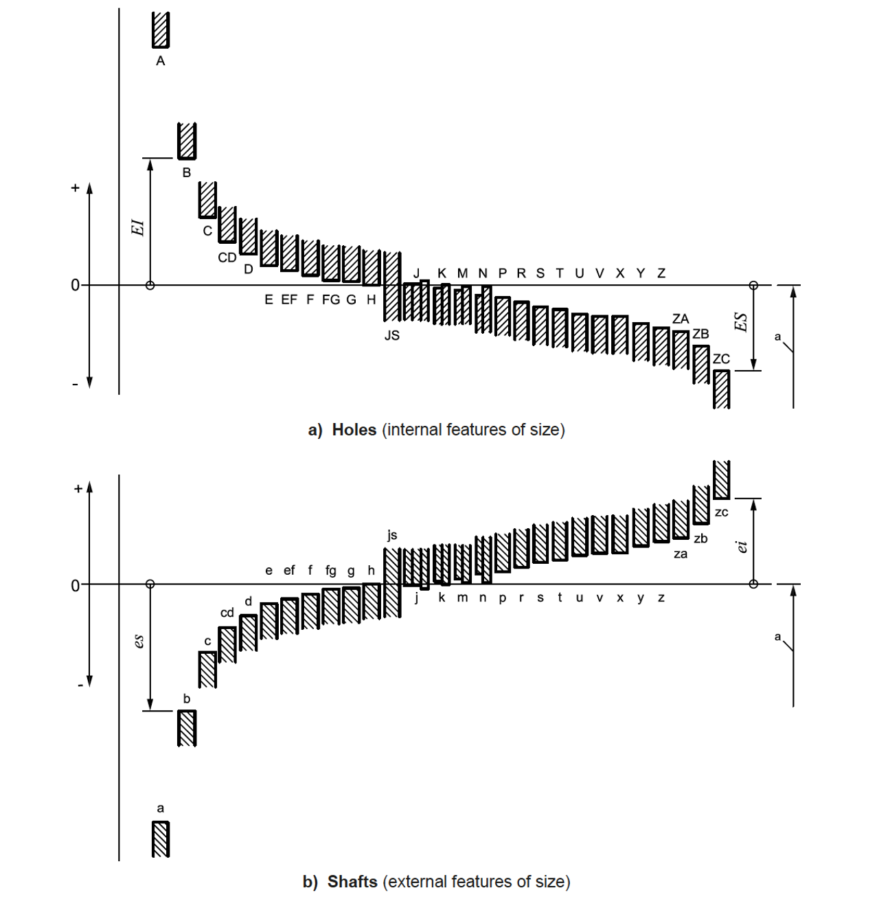
The ISO tolerance system is designed to standardize manufacturing tolerances for both holes and shafts, ensuring compatibility across different parts and assemblies. Each tolerance is defined by a combination of a letter and a number:
- The letter signifies the position of the tolerance zone relative to the nominal size. For holes, this is indicated by uppercase letters (A, B, C, … H, etc.), and for shafts, lowercase letters are used (a, b, c, … h, etc.).
- The number indicates the tolerance grade, which represents the size of the tolerance zone. Smaller numbers mean tighter tolerances, and the range goes from IT01 (very tight) to IT16 (very loose).
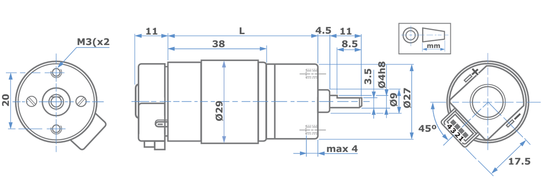
Below is an example of an engineering drawing from the datasheet of a DC motor. You can see that the tolerance defined for the shaft is “h8”
Below is an example of how to apply the matching process to achieve different types of fits: clearance, interference, and transition. The h8 tolerance indicates a shaft where the size can vary slightly below its nominal diameter, aiming for precise but unrestrictive fits.
Clearance Fit Example
-
Goal: A shaft rotates freely within a hole, used in applications where easy assembly and disassembly are required, along with minimal resistance to rotation.
-
Shaft Tolerance: Assuming a shaft is designated as “h8”. The “h” indicates a basic size with a zero to negative deviation, allowing for a very small decrease from the nominal diameter, ensuring it will fit within any standard-sized hole without modification.
-
Hole Tolerance: For a matching hole where the shaft needs to rotate freely (clearance fit), one might choose “H8” or “H9”. The “H” designates a hole slightly larger than the nominal size, allowing for free movement. The number indicates the tolerance grade, with “H8” providing a standard fit and “H9” offering a looser fit, enhancing the clearance for applications requiring minimal friction.
Interference Fit Example
-
Goal: A shaft is press-fit into a hole, requiring force to assemble. This fit is chosen for applications where the connection must be secure without the need for additional fasteners.
-
Shaft Tolerance: With the shaft designated as “h8”, achieving an interference fit requires a hole tolerance that results in the hole being slightly smaller than the minimum size of the shaft.
-
Hole Tolerance: To achieve this, a tolerance tighter than “H8”, such as “H7”, might be used. This selection aims to make the hole slightly smaller or at the maximum just equal to the smallest possible size of the h8 shaft, thus requiring force to assemble and creating an interference fit.
Transition Fit Example
-
Goal: A fit that allows for assembly or disassembly by hand but ensures a snug fit, typically used where alignment is critical but some adjustability is needed.
- Shaft Tolerance: The “h8” shaft, by definition, offers a small negative deviation from the nominal size, potentially allowing for both slight clearance and interference, depending on the actual size within the tolerance range.
- Hole Tolerance: To match the h8 shaft for a transition fit, selecting “H7” can provide an optimal balance. This pairing might result in either a slight clearance or minimal interference, depending on the actual sizes within their respective tolerance ranges. The “H7” tolerance ensures the hole is not too tight on the larger end of the h8 shaft but may require light force for assembly at the lower end of the shaft’s tolerance.
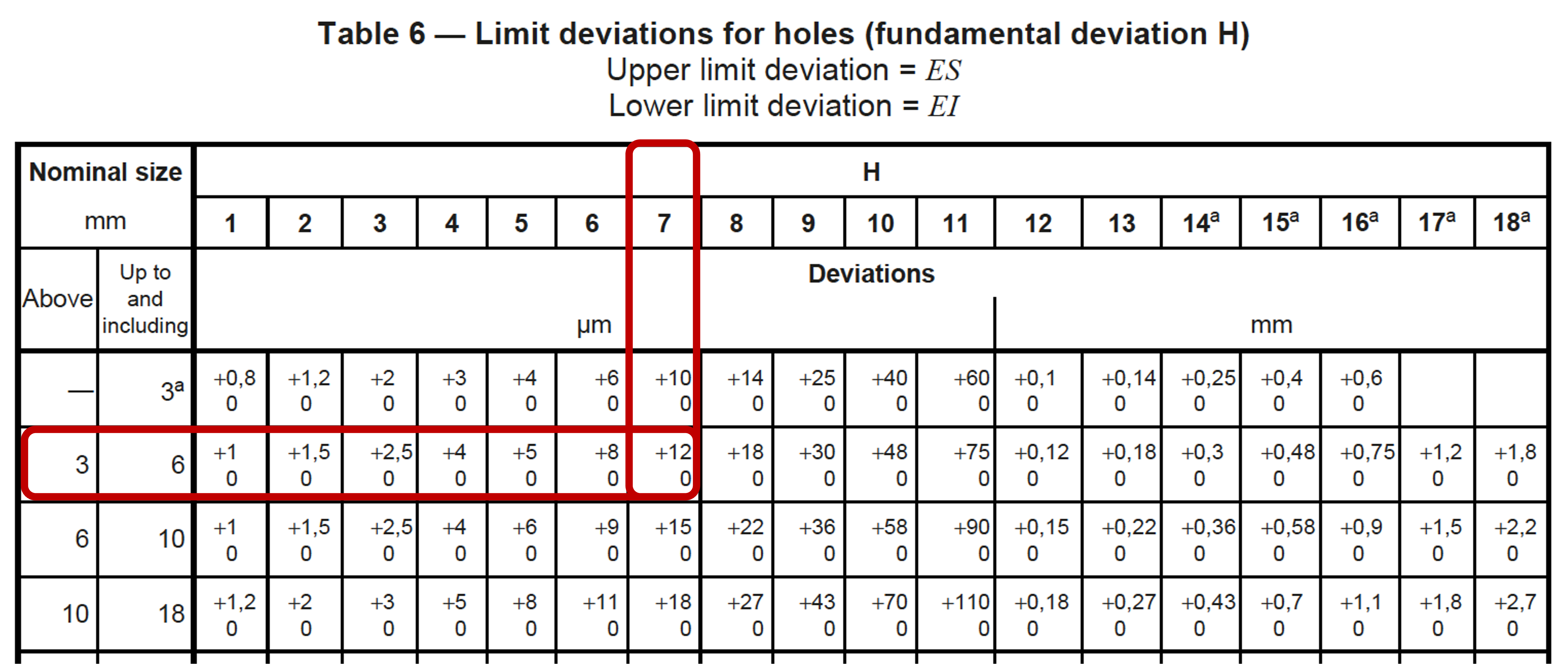
The ISO tolerances standard includes charts that define the tolerances. Following on from the previous example, to size a hole with “H7” tolerance:
- Download the
BS EN ISO 286-2-2010file above. - Find the appropriate Limits deviation table. In this case it is
Table 6-Limit deviations for holes (fundamental deviation H)(page 12). - The left most column shows the nominal size. According to this example, this is 4mm, therefore the
second rowmust be used. - Find the column corresponding to
H7. - The intersection will show the appropriate tolerance limits.
Step 5: Complete Mechanism Design
By this stage you should have everything you need to design the full mechanism. The process may be iterative as you adjust the design based on the available motors.
Extension Tasks:
If you have time at the end of the lab you may want to design a holding bracket to keep the motor in place.
References
-
https://www.core77.com/posts/59362/Explaining-Hardware-Set-Screws
-
https://sdrobots.com/tech-thursday-018-couple-motor-shafts-components/\
-
https://teknic.com/securing-mechanics-motor-shafts/