Introduction to Assembly Programming
Overview
In these lab sessions you will learn about the development of embedded systems. In particular, you will learn how to:
- Use Proteus VSM software to simulate microprocessors and their associated circuitry.
- Use an integrated development environment (IDE) MPLABX.
- Write assembly code for the PIC16F84A microprocessor.
- Compile assembly code.
- Use the PICkit3/4 to program the PIC microprocessor.
- Connect the PIC16F84A to various other components and perform various input and output operations.
Resources
Software
You will be using two software suites:
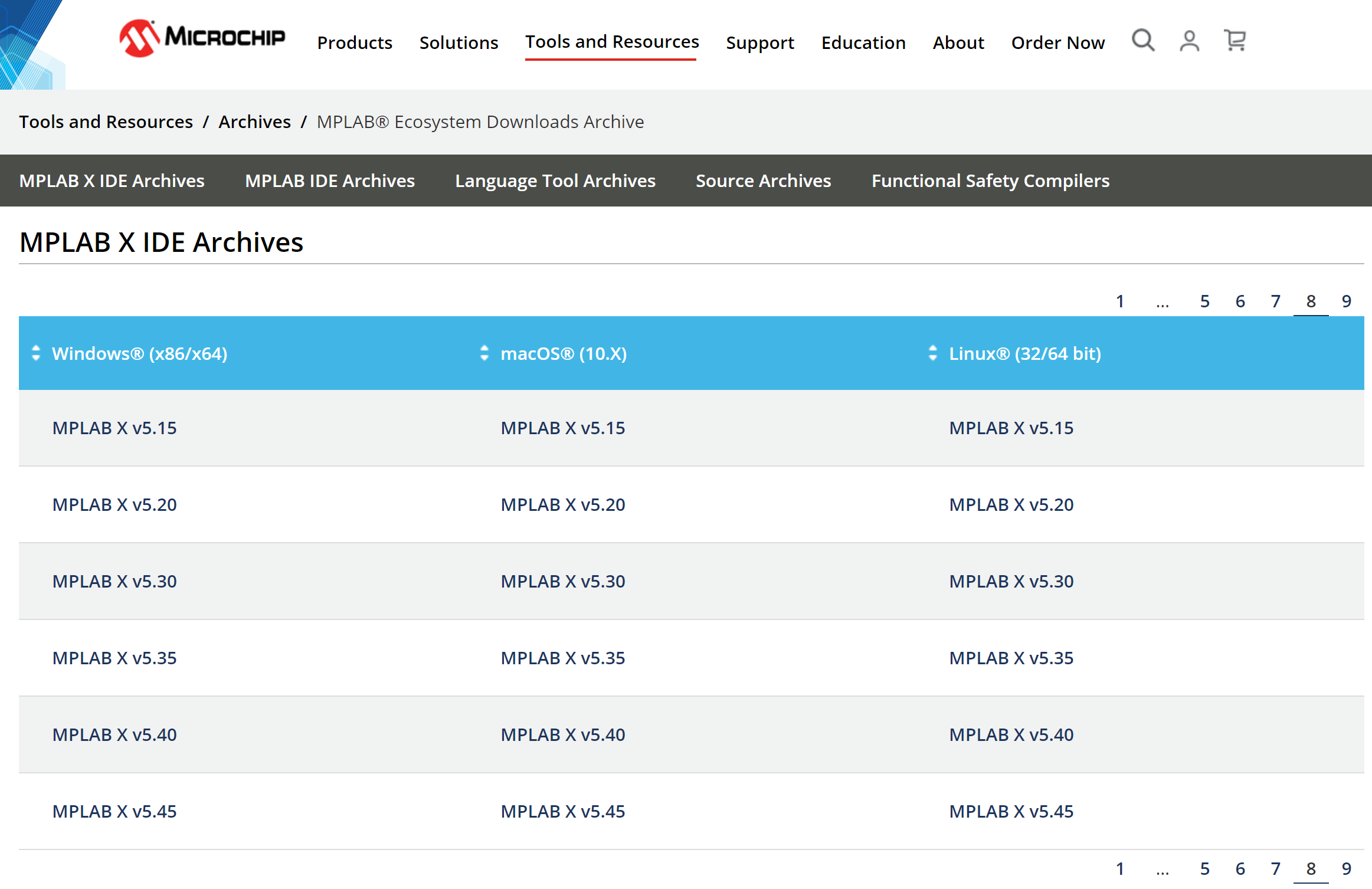
- MPLAB® X Integrated Development Environment (IDE). The version must be no more recent than v5.35 since later versions do not support compilation of assembly code.
- Download MPLAB X v5.35 from the MPLAB X IDE Archives at https://www.microchip.com/en-us/tools-resources/archives/mplab-ecosystem#.
- Click on downloaded .exe file.
- If requested, log on with administrator privileges.
- This start installation wizard » click next.
- Accept terms and conditions.
- Choose installation directory (default is likely to be fine).
- Ensure MPLAB X IDE and 8-bit MCUs are ticked (you can tick others if you want, depending on how much storage space you have).
- Start the installation.
- Accept any security requests.
- You will then have the option to further install the XC8 compiler for 8-bit PIC microcontrollers.

- Proteus Virtual System Modelling (VSM). See previous lab script for installation instructions.
Hardware
The following hardware will be used and is available in the laboratory or electronics store:
- Computer with MPLABX v5.35 and Proteus installed. They need not be the same machine. One could be on your laptop.
- PIC16F84A in-house development board.
- Breadboard to build circuit.
- Microchip PICkit3 or PICkit4 programmer with USB cable.
- Kingbright SA08-11EWA seven segment LED displays.
- Push button switches.
You will sign out boxes of the required equipment from the lab technicians to allow you to work on the labs in your own time when the labs are closed. Alternatively, the boxes may also be left in the labs.
On-line Resources
Electronic resources can be found through the links below:
- PIC16F84A microprocessor datasheet (Full version).
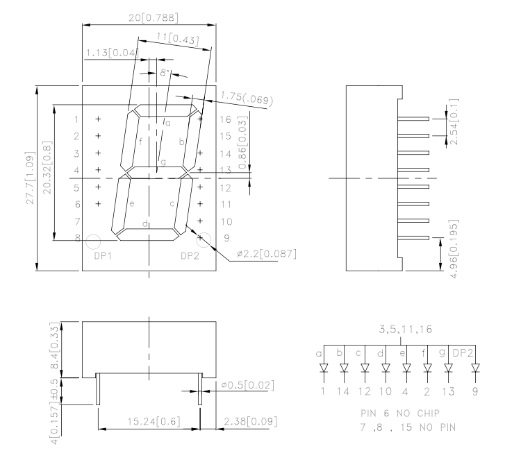
- SA08-11EWA seven segment display datasheet.
- Reference manual for MPASM the microchip assembly language.
The PIC16F84A development board
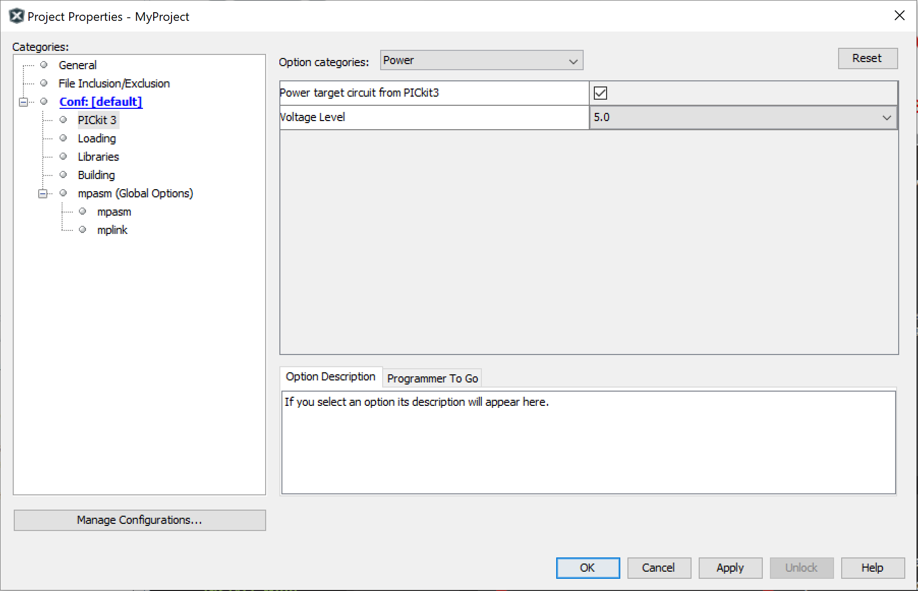
We are not going to use the PIC directly but we will use a small board that has been developed in-house as shown in Figure 1.
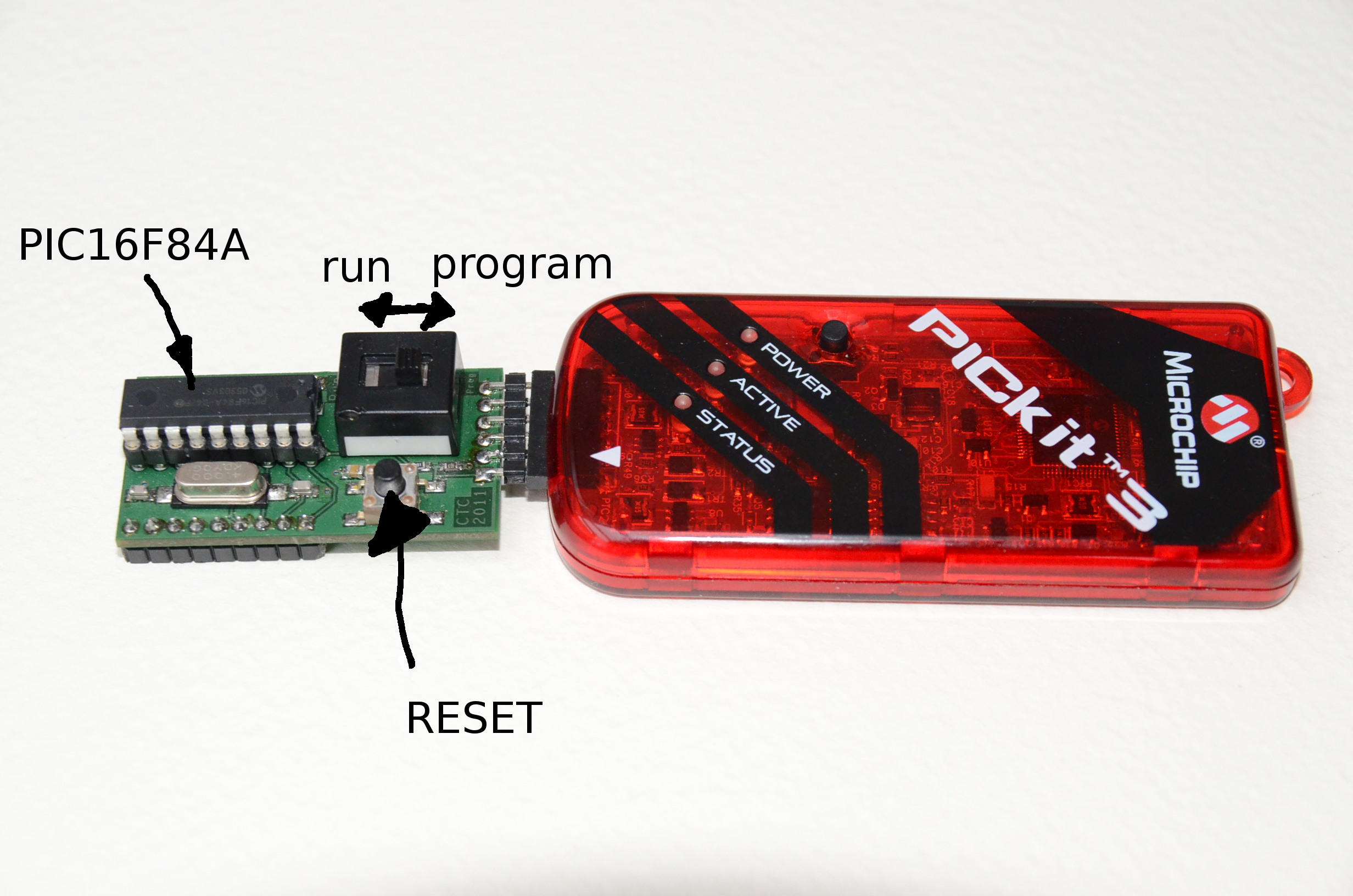
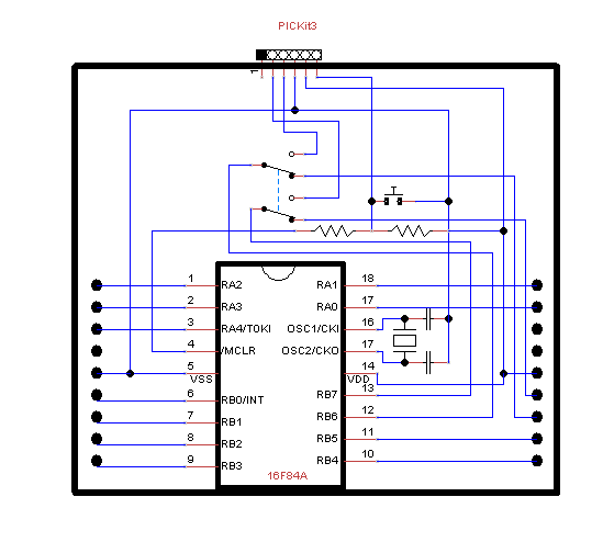
This board includes some circuitry as shown in Figure 2 to make your life slightly easier, and includes:
- A crystal oscillator (the main reason for using a PCB rather than bread board is to make the connections reliable).
- Connector for the PICkit3.
- A switch for connecting the PIC to the programmer.
The programmer users pins RB6 and RB7 of the PIC so these will be disconnected from your circuit when the switch is in programming mode (See Figure 2.). If you don't use these pins you can leave the switch in program mode.
- A push button reset.
How to get help
The first place to find help is within this lab script. Each activity describes the key information that you require, and, especially in the first parts, gives you screen shots walking you through the process.
The Troubleshooting section has a list of common problems that have been compiled over years of students following this and similar labs.
If you are sure that your problem is not in the FAQ section, you should consult a demonstrator.
Activity 1 - a first PIC program
This first activity will get you started with the hardware and software by leading you through step-by-step. By the end you will:
- Know how to use MPLAB X and Proteus to write a simple programme to control a PIC microprocessor.
- Be able to build a simple electronic circuit to control LEDs on the microprocessor output pins.
Getting started
This section shows you how to get started with the MPLAB X Integrated Development Environment.
You can create a project using MPLAB X as follows:
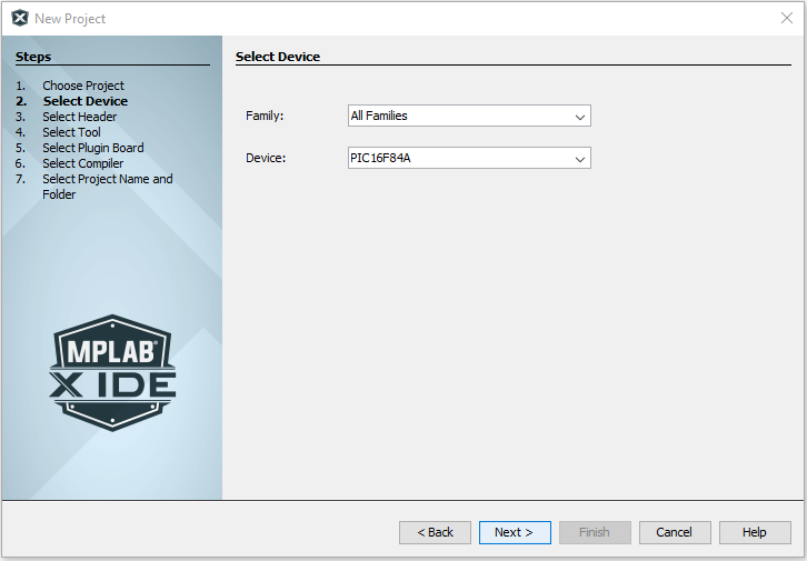
- From the main menu select: File > New Project & select Standalone Project
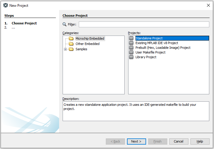
- Select the PIC16F84A device.
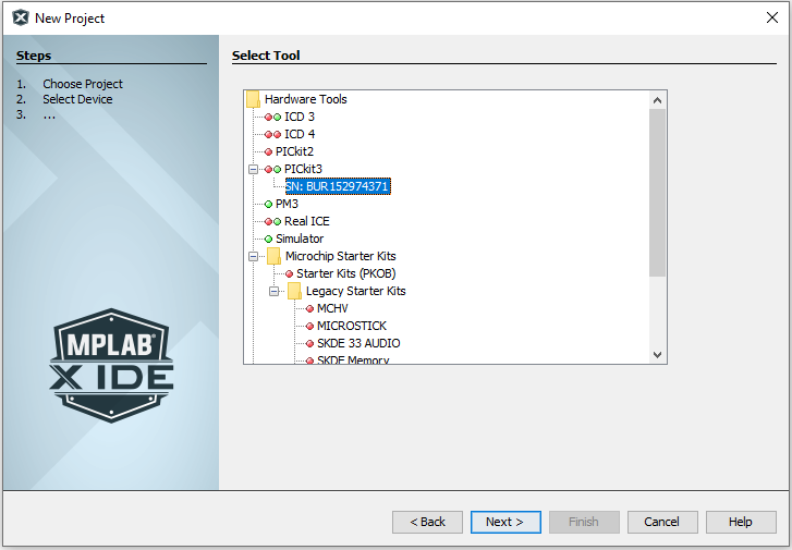
- For Hardware tools select PICkit3 or PICkit4. If the PICkit is already connected to the computer, you will see its serial number, as in the screenshot below.
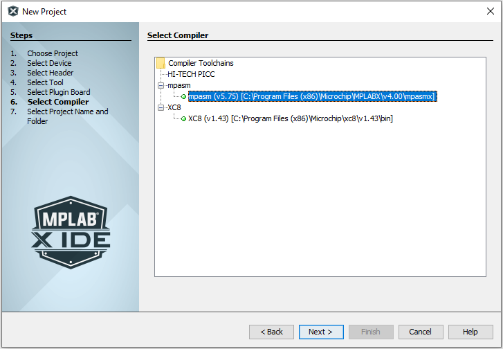
- For the compiler select mpasm
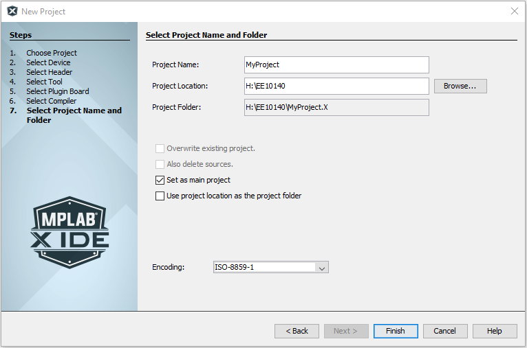
- The project name can be anything you like! The folder should be set to
H:\MPLABXProjects\or similar.
MPLABX does not like network file names like \\campus\myfiles
To create a new file for your assembly code:
- Right-click on your project Source Files
- Select New > pic_8b_simple.asm and then choose a filename (best not to use spaces in filename)

You will need to power your circuit. The best and easiest way to do this is to use the PICKit to directly power the PIC. This route also ensures that you do not damage the components. By default this feature is not enabled.
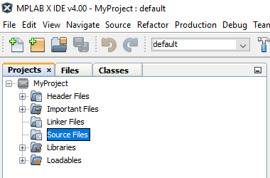
To enable the power using MPLABX:
- Right click your project in the Projects TAB and select Properties. This should bring up the Project Properties dialogue.
- In the Categories Pane, select Conf: PICKit 3
- From the Option categories: select Power
- Enable the power by ticking the Power target circuit from the PICKit 3
Notes:
- Power can be taken from the Vss (0V) and Vdd (5V) pins of the PIC development board to supply other components.
- The PICkit has limited power (about 30 mA) but it has been tested for the examples and exercises in this lab and had no problems (yet).
- If you try to draw more than this (probably a wiring error by you) the device may not work correctly but at least you will not damage anything!
TIP: If you put the wires for the power supply connections underneath the PIC board then it will leave space for the other connections.
The PIC and PICKit3/4 are quite robust. Under normal use the PIC will not get hot. If it does get warm switch off and check your connections.
You will be working with a single assembly code program for each example/exercise.
To create a new program you can either:
-
Create a new project for each program (remember to set this as your main project)
OR
-
Remove the source file from the project (using right click) and add a new file with a new name.
DO NOT have multiple .asm files in the same project.
Turning an LED on
In your pair, one person could focus on MPLAB and the other on Proteus.
But do switch round so you understand both.
In this section you will:
- Use MPLAB X/Proteus to compile and run an assembly code program.
- Include common ‘defines’ in a program and set the configuration bits in the PIC.
- Set up an output port and output some data to it.
- Learn how to drive an LED from the PIC and loop forever.
Hardware
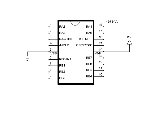
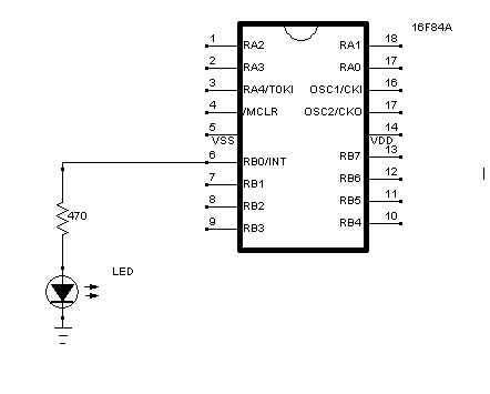
The PIC16F84A is quite a robust chip and will survive some abuse but you should try to do things properly. Limiting the current to $< 10\ mA$ through the LED should provide enough light and is within the capabilities of the PIC.
The current can be limited by using a resistor in series with the LED. The output voltage of the PIC is around $5\ V$ and there will be a volt drop across the LED. For this application a $470\ \Omega$ resistor in series with the LED should work fine.
Software
Programs for the PIC can be written in assembly code or C.
For the first part of the course, the programs for the PIC will be written in assembly code. An understanding of how to program at the lowest level is very useful to understand how everything works. For the second part of the course you will create programs using C.
In either case programs end up as machine code which is loaded into program memory.
The program turnOnLED.asm (shown below) is an assembly language program that will turn on an LED connected to pin RB0.
;*************************************************************************
; Example program showing how to output to PORTB RB0
; - sets up PORTB as output
; - outputs to pin RB0 via PORTB
; - loop
;*************************************************************************
;
; We include P16F84A.INC to define some useful constants

#include P16F84A.INC

; The next line sets up some fuses in the PIC
; for example _XT_OSC sets up the PIC for a crystal oscillator
; _WDT_OFF turns off the watch dog

__config _XT_OSC & _WDT_OFF & _PWRTE_ON

; PIC always starts executing at address 0
; so this is were we want our code.

ORG H'0' ;defines were the code is to be loaded in memory
bsf STATUS,5 ;select bank 1
movlw B'00000000' ;set up all PORTB as outputs
movwf TRISB ;
bcf STATUS,5 ;select bank 0
loop
movlw B'00000001' ;output to PORTB
movwf PORTB
goto loop ;loop forever
end- Within the program, all text following a semi-colon are comments and are not converted to machine code.
- The #include includes the contents of another file. In this case, P16F84A.INC defines some important constants for the PIC we are using. The exact location of this file will depend on your setup. On my computer using windows XP it can be found in the folder: C:\Program Files\Microchip\MPLABX. The file defines names for addresses of the file registers and constants that are useful for setting bits. Using these names makes your code more readable and portable.
Programming the microprocessor with MPLAB X
When you use the MPLAB X run command there are a few stages:
- MPLAB X uses the program
mpasmto assemble your assembly code into machine code. If this stage fails then you will get an error message and the process stops at this stage. - If compilation is successful MPLAB X will try to use the PICKit to send the machine code (binary data) to the PIC. This stage will fail
if you have not:
- Connected the PICkit to the PIC,
- Set the switch for programming and provide power to the PIC.
You should get some error messages if this stage fails.
Procedure summary
- Set up the circuit with the PIC and the LED
- Create a source file for your program in the project and type turnOnLED.asm into it.
- To run the program:
- Set the programming switch to enable programming
- Run > Run main project
If you have done things right then the LED should switch on. If you have a problem getting this circuit to work consult the FAQ.
Test your understanding
Exercise 1.1
The breadboard allows you to easily connect your circuit to the microcontroller. Using a multimeter, work out how the breadboard is designed.
Note, some holes are connected to neighbouring holes in one direction, and others in the perpendicular direction. Sketch a schematic of the breadboard showing which holes are connected together.
Exercise 1.2
Following the instructions in the sections above, build the circuit and run the program. The LED should switch on.
Exercise 1.3
Add more LEDs to pins RB1, RB2, RB3 and modify the program to turn on RB1 and RB3 only.
Exercise 1.4
Modify the program to switch on RB0 and RB2 only.
Exercise 1.5
Switch your LEDs to pins on PORTA (i.e. RA0-RA3) and modify your program to switch them on.
Hint: You will need to set the pins you are using as outputs first by writing to TRISA and TRISB.
Activity 2 - Driving a 7-segment display
Objectives
The purpose of this activity is to use the PIC microcontroller to control the LEDs within a seven segment display and thus use multiple output pins simultaneously.
The 7-segment display
Details about the Kingbright SA08-11EWA can be found in the data sheet. The anodes are all connected together. The output ports can be used as sinks to pull each cathode down to 0 V. This means outputting 0 will turn on a segment. The relevant information is shown in Figure 1.
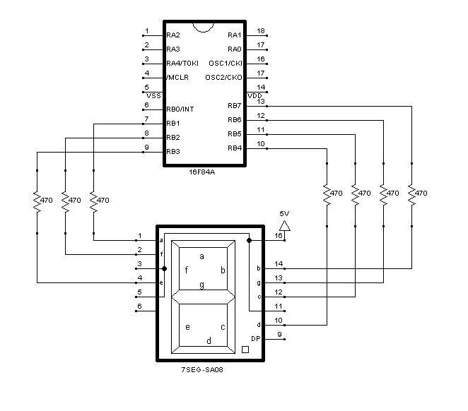
In Proteus, the component is called 7SEG-COM-ANODE. But note that the configuration of the pins is different.
You will need to disconnect the LED from the previous circuit. Connect the 7-segment display: the common anode to the +ve supply and each cathode of the segments to pins RB1-7 of PORTB via a resistor to limit the current ($470\ \Omega$ is OK), as shown in Figure 2.
Test your understanding
Exercise 2.1
Create a new project and write a program to display a number on the display. Modify your program to display a different number.
Exercise 2.2
Explain what happens if you leave the programming switch in programming mode.
Exercise 2.3
Why do we use series resistors on each output?
Activity 3 - Reading data from pins
Objectives
The purpose of this activity is to use some of the PIC microprocessor pins as inputs so that information can be received from the outside world. This information will then be used to control the output pins. You will learn about the role of pull up/down resistors to avoid poorly defined voltage states.
Connecting up switches
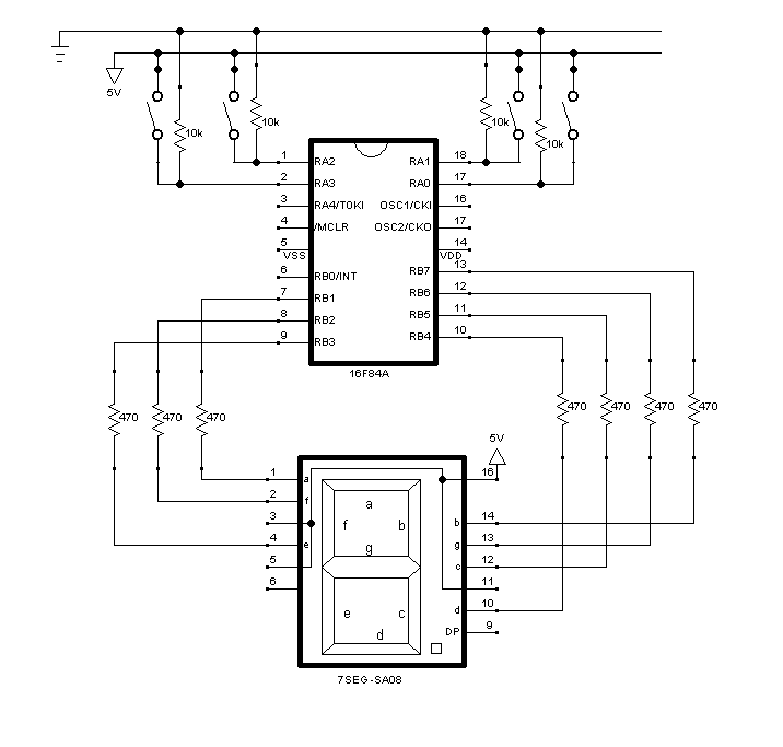
We use switches with pull down resistors as inputs as shown in Figure 1.
In Proteus you can use SWITCH and RES and specify the resistance by double-clicking on the component.
Polling pins
The readPORTA.asm program below sets up PORTA as an input. The program then loops reading from PORTA and putting the data onto PORTB.
; Example program
; set up PORTB as output
;        PORTA as input
;
; loop
;        read PORTA
;        output to PORTB

#include P16F84A.INC
 __config _XT_OSC  &  _WDT_OFF & _PWRTE_ON

ORG     h'0'            ;defines where the code is to be loaded in memory

    clrf    PORTA         ; clear output latches
    clrf    PORTB         ;

    bsf     STATUS,5          ; select bank 1
    movlw   B'00000000'       ; set up port B as all outputs
    movwf   TRISB

    movlw   B'00001111'       ; set up port A 0-3 as inputs
    movwf   TRISA
    bcf     STATUS,5          ; select bank 0

loop
    movfw   PORTA         ; input PORTA
    movwf  PORTB             ;  output to PORTB
    goto   loop              ;  loop forever
end Test your understanding
Exercise 3.1
Use a multimeter to determine how the switch is connected whilst open and whilst closed. Draw a diagram showing how the switch works.
Exercise 3.2
Create and test the circuit with the code in readPORTA.asm, making sure it works by setting switches and observing
the segments changing. Do this in Proteus and with hardware.
Exercise 3.3
Why does the switch connected to RA0 have no effect.
Activity 4 - Binary to decimal converter
Objectives
In this activity you will display the seven segment character for the binary number represented by the buttons. This will require:
- Converting a 4-bit number to seven segment code for a hexadecimal number
- Using a programmed jump to implement a look up table
- Learning how to use a subroutine
Creating a look-up table
The following code fragment illustrates a look-up table; one way of converting a 4-bit number to an 8-bit number.
...; w contains the 4 bit number
call conversion
; w now contains the 7 segment code
; convert 4bit number in w into a seven segment code.

conversion
    addwf PCL ; add w to the PC (jump)
    retlw B'10111110' ; 0 ; return 7 seg code.
    retlw B'00001100' ; 1
    retlw B'11011010' ; 2
    retlw B'11110010' ; 3
    retlw B'11100100' ; 4
    retlw B'01110110' ; 5
    retlw B'01111110' ; 6
    retlw B'10100010' ; 7
    retlw B'11111110' ; 8
    retlw B'11100111' ; 9
    retlw B'11101110' ; A
    retlw B'01111100' ; B
    retlw B'00011110' ; C
    retlw B'11111000' ; D
    retlw B'01011110' ; E
retlw B'01001110' ; F...Exercise 4.1
- From the datasheet, find out what the PCL register is and the instruction retlw.
- Work out how the code converts one value within the working register to another.
Test your understanding
Exercise 4.2
By modifying your previous programs write an assembly program to convert your input on PORTA (representing a binary number) to the correct seven segment code using a look-up table. Run your program and check that the number on the seven segment display correctly corresponds to the binary number input.
You will need to modify the binary numbers in the code to turn the correct LEDs on within your particular circuit. The correct code will depend on how you have wired up the 7-segment display. Because we are using the pins as sinks for current you might need to invert these numbers and double check that the correct LEDs are lighting up.
Activity 5 - Flashing using a delay
Objectives
We often want to wait for a while in a procedure. One way to do this is to make the PIC execute lots of instructions.
In this activity you will learn how to make a delay by using multiple nested loops and using a set of initial counters to control the delay time.
For this, it is important to know that the PIC development board has a 4 MHz crystal oscillator and that each instruction cycle is 4 clock cycles.
So that Proteus models the hardware properly, you will need to change the clock frequency from the default value of 1 MHz by clicking on the microprocessor in the schematic.
Delay routine
The following code shows how we can use a delay routine to make the 7-segment display flash.
The values in the registers DELAY_COUNT1, DELAY_COUNT2 & DELAY_COUNT3 determine the length of the delay.
#include P16F84A.INC
 __config _XT_OSC  &  _WDT_OFF & _PWRTE_ON

;File Registers used by delay subroutine
DELAY_COUNT1    EQU     H'21'
DELAY_COUNT2    EQU     H'22'
DELAY_COUNT3    EQU     H'23'

ORG   h'0'

   bsf    STATUS,5          ; select bank 1
   movlw  B'00000000'       ; set up port B as all outputs
   movwf  TRISB
   bcf    STATUS,5          ; select bank 0

;  flash the output ON then OFF
loop
   movlw  B'11111111'       ; output ones to PORTB
   movwf  PORTB
   call   delay
   movlw  B'00000000'       ; output zeros to PORTB
   movwf  PORTB
   call   delay
   goto   loop              ; loop forever

; program delay
delay
   movlw  H'FF'             ; initialise delay counters
   movwf  DELAY_COUNT1
   movlw  H'FF'
   movwf  DELAY_COUNT2
   movlw  H'03'
   movwf  DELAY_COUNT3
delay_loop
   decfsz DELAY_COUNT1,F    ;  inner most loop
   goto   delay_loop        ;  decrements and loops until DELAY_COUNT1=0
   decfsz DELAY_COUNT2,F    ;  middle loop
   goto   delay_loop
   decfsz DELAY_COUNT3,F    ;  outer loop
   goto   delay_loop
   return

end Test your understanding
Exercise 5.1
Work out how many instructions are executed in 1 second?
Exercise 5.2
Use the delayFlasher assembly code to get all the 7-segment display to flash on and off, i.e. a flashing 8.
Exercise 5.3
Modify your program to make the display flash at 1 Hz.
Exercise 5.4
Modify your program to make the display flash at 10 Hz.
Troubleshooting
General problems
- Is the LED the correct way round?
- Do you have an .asm extension on your source file?
- Have you tried to use a network file path? e.g.
\\campus\myfiles - Does your code include an end statement? Is this in the right place?
- Do you only have one source file?
- Have you switched on the power?
- Have you copied code from Moodle? If so, the software might not have recognised the apostrophes in the code. To solve this, delete and retype all apostrophes.
- Have you used the correct value resistors?
I get an error message
Firmware Suite Version.....01.26.81
Firmware type..............Midrange
Target device was not found. You must connect to a target device to use PICkit 3.
Check:
- You have connected the PICkit3/4 correctly
- You have enabled the PICKit3/4 to supply power in MAPLAB X.
- Check PIC is inserted properly.
Target Device ID (0x0) does not match expected Device ID (0x560).
This could be caused by 2 things:
- You have the programming switch in the wrong setting.
- The PIC is broken (try with another PIC).
If all fails try:
- Disconnecting the USB.
- Restart MPLAB X.
I see error messages that there is insufficient power.
- Try plugging the PICKit3/4 into the USB port on the back of the computer
- Reduce the voltage from 5 V down to 4.75 V, for example.
My circuit almost works but does strange things (sometimes?)
This can be because you are reading from a pin that has not got a pull up/down resistor. If the input is high impedance and the connection is floating it will simply pick up any electrical noise (useful if you want a random signal generator but usually not a good idea).
Also check all the connections to breadboard are sound and there are no touching wires.
My circuit does not work!
- Check your connections.
- Check your program (borrow the hardware from someone who has the example working to test your code). Or check in Proteus.
- Check your components are working.