The Three Phase Induction Motor
Power Electronics and Electrical Machines
Aim
To investigate the operation of a three-phase induction motor.
Introduction
Most electric motors found in industry are induction types, with single-phase motors used for smaller sizes and three-phase motors for larger sizes. Three-phase induction machines are divided into two main types: wound rotor and squirrel cage, with the squirrel cage being the most common. The machine used in these experiments is a squirrel cage rotor type.
Objectives
- To build a simulation model of an induction machine.
- To conduct a load test to determine the machine’s operating characteristics.
Engineering skills
The student will gain practical experience in the following areas:
- Keeping a record of work done in the form of a report.
- Simulating an AC motor.
- Taking measurements.
- Calculating results.
- Interpreting and explaining results.
Procedure
Work through the following exercise, clearly detailing in your report, with the assistance of circuit diagrams, your actions and the results obtained. Insert labelled printouts into your report. Answer questions and note observations as you proceed. If you have any uncertainties about building and running the simulation, please email fd506@bath.ac.uk.
It is very important to comment on and explain any results obtained during the exercise.
When answering questions, refer to the data and results collected throughout the exercise.
Theory
Machine Construction
The induction machine consists essentially of a stator, which in this case, carries a three-phase winding, and a rotor. There are two main types of rotors: the squirrel-cage rotor and the wound rotor, as shown in (a) and (b), respectively. In the squirrel-cage rotor, solid conducting rods are inserted into closed slots, and at each end, the rods are connected to a heavy short-circuited ring. This forms a permanently short-circuited winding that is practically indestructible. The squirrel-cage rotor is inexpensive and robust but has the disadvantage of low starting torque.
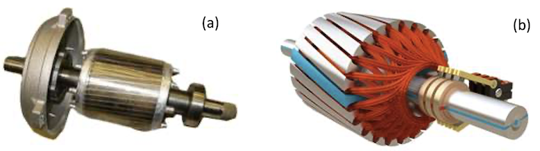
The wound rotor has a three-phase winding with the same number of poles as the stator; the ends of the rotor winding may be brought out to three slip rings. The advantage of the wound rotor machine is that an external starting resistance can be connected to the slip rings to give a large starting torque. This resistance is then reduced to zero as the machine accelerates to its operating speed.
Operation
When a three-phase winding is energised from a balanced three-phase supply, a rotating magnetic field is established, traveling at synchronous speed $n_s$ (rpm) given by:
\[\begin{equation} \label{eq:SynchSpeed} n_s = \frac{f}{p} \times 60 \end{equation}\]Where $f$ (Hz) is the supply frequency and $p$ is the number of pole pairs ($\frac{poles \space number}{2}$).
Because the rotating magnetic field of the stator cuts the rotor conductors, currents are set up in the rotor windings at slip frequency $f_s$. The steady-state rotor speed is normally slightly less than synchronous speed so that the motor runs with a per-unit slip $s$, defined as:
\[\begin{equation} \label{eq:Slip} s = \frac{n_s - n_r}{n_s} \end{equation}\]where $n_r$ is the rotor speed.
At standstill, $n_r = 0$ and $s = 1$. With the machine ($p=2$, $f=50$ Hz) running light the rotor speed will be in the region of 1490 rpm and $s = 0.0067$.
The rotor and stator fluxes travel at the same speed. The axes of the stator and rotor fluxes have an angular displacement, resulting in a torque that acts on the rotor, causing it to accelerate in the same direction as the stator field. When the machine is loaded, the rotor speed drops, which increases the value of the slip. With increased slip, the rotor-induced currents increase in frequency, and the machine produces a higher electro-mechanical torque to drive the load. The torque produced is limited to a maximum value called the pull-out torque.
Machine performance is often depicted by a torque-speed curve, showing the variation of machine torque with speed or slip. To obtain the torque-speed curve, the machine can be load tested. Alternatively, these characteristics can be determined through calculations using the machine’s approximate equivalent circuit.
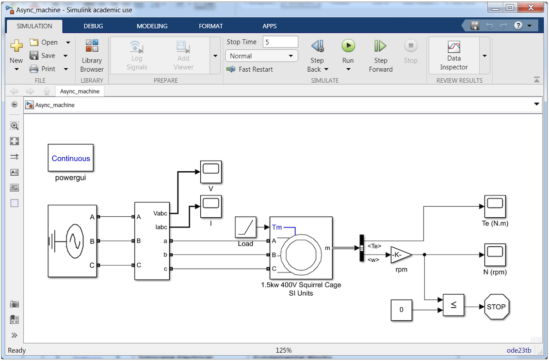
Simulink blocks
The Simulink blocks used in the project are as follows:
| Module | Function | Block Location | |
|---|---|---|---|
| 1 | 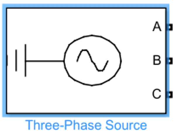 |
Provide three phase power | Simscape / Electrical / Specialized Power Systems / Fundamental Blocks / Electrical Sources |
| 2 | 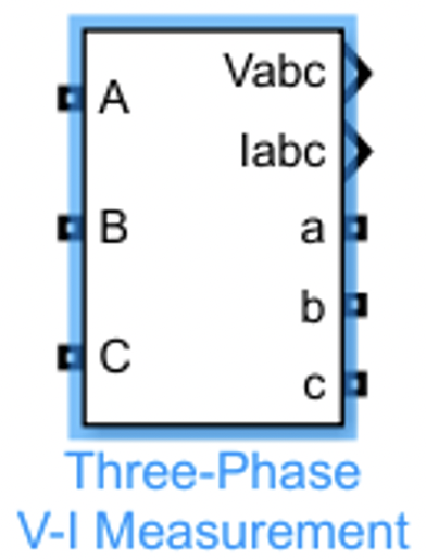 |
Measure three-phase currents and voltages in circuit | Simscape / Electrical / Specialized Power Systems / Fundamental Blocks / Measurements |
| 3 |  |
Display signals generated during simulation | Simulink / Commonly Used Blocks |
| 4 | 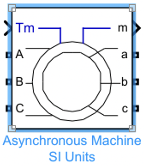 |
Model the dynamics of three-phase asynchronous machine, also known as induction machine | Simscape / Electrical / Specialized Power Systems / Fundamental Blocks / Machines |
| 5 |  |
Generate constantly increasing or decreasing signal | Simulink / Sources |
| 6 |  |
Select signals from incoming bus | Simulink / Commonly Used Blocks |
| 7 |  |
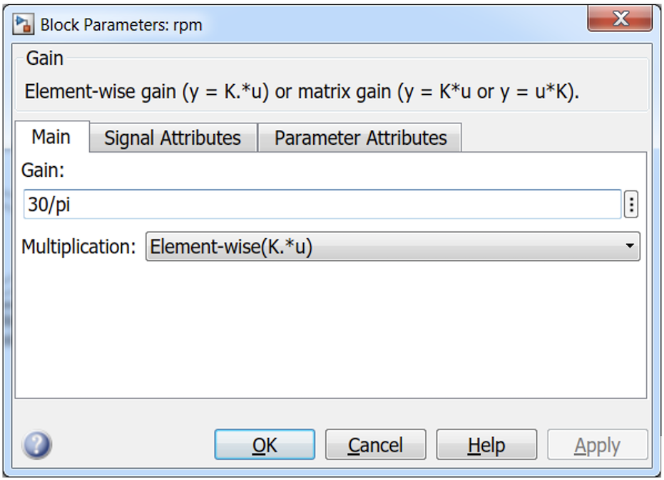
Multiply input by constant | Simulink / Commonly Used Blocks |
| 8 | 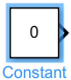 |
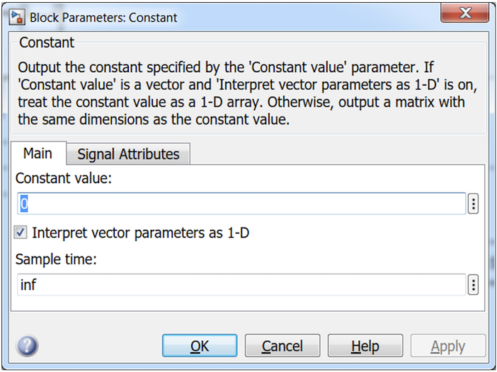
Generate constant value | Simulink / Commonly Used Blocks |
| 9 |  |
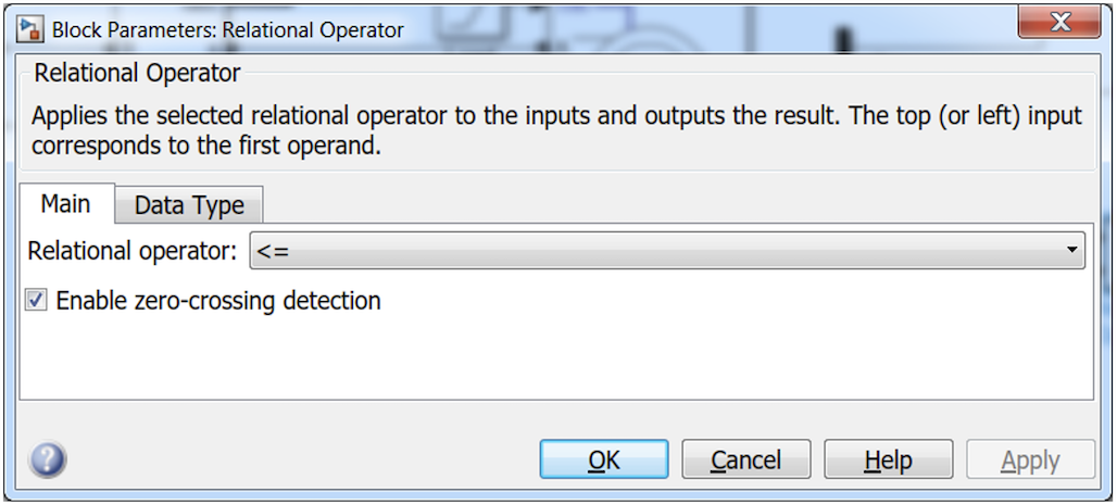
Perform specified relational operation on inputs | Simulink / Commonly Used Blocks |
| 10 |  |
Stop simulation when input is nonzero | Simulink / Sinks |
| 11 | 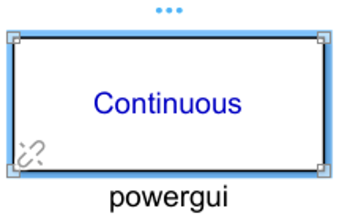 |
Environment block for Simscape Electrical Specialized Power Systems models | Simscape / Electrical / Specialized Power Systems / Fundamental Blocks |
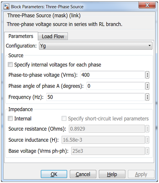
Three-Phase Power Source
The Three-Phase Source block implements a balanced three-phase voltage source with an internal R-L impedance. The three voltage sources are connected in Y with a neutral connection that can be internally grounded (Yg) or made accessible. Double click the three-phase power source block to setup three parameters “Phase-to-phase voltage (Vms):”, Phase angle of phase A (degrees):” and “Frequency (Hz):”, as shown in . In this study, “Yg” is selected, which means the three voltage sources are connected in Y to an internally grounded neutral.
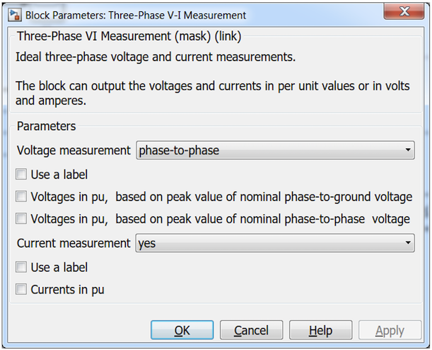
Three-Phase V-I Measurement
Instead of using separate voltage and current measurement blocks, an integrated three-Phase V-I Measurement block is used to measure instantaneous three-phase voltages and currents. When connected in series with three-phase elements, it returns the three phase-to-ground or phase-to-phase peak voltages and currents. In this exercise, Phase-to-phase voltage and current measurements are taken, as shown in .
Scope
Three-Phase Asynchronous Machine
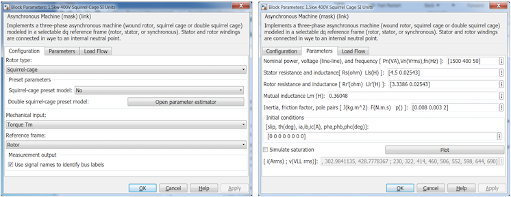
Asynchronous Machine blocks with either Pu Units or SI Units are available in Simulink Library. The block with SI units is selected in this simulation. The machine used in the simulation is 1.5kw, 400V, 50Hz, 4 poles (2 pole pairs) squirrel-cage induction motor. The parameters of the machine are shown in .
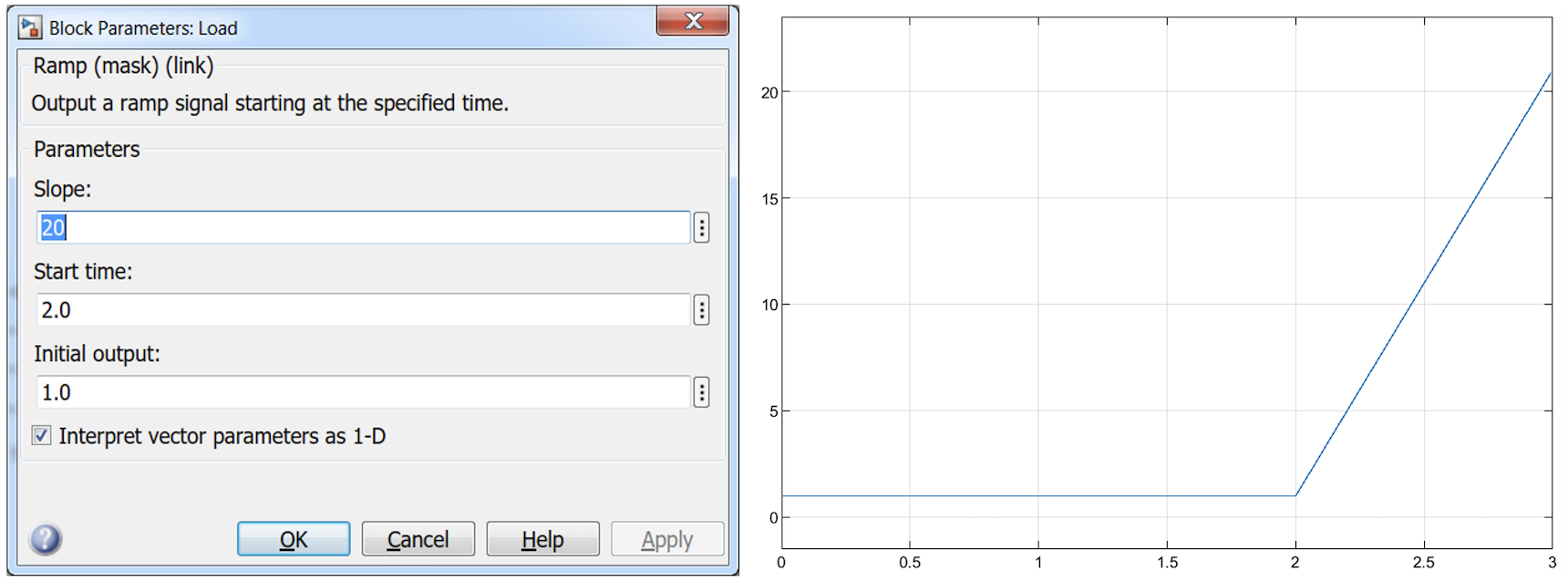
Ramp Block
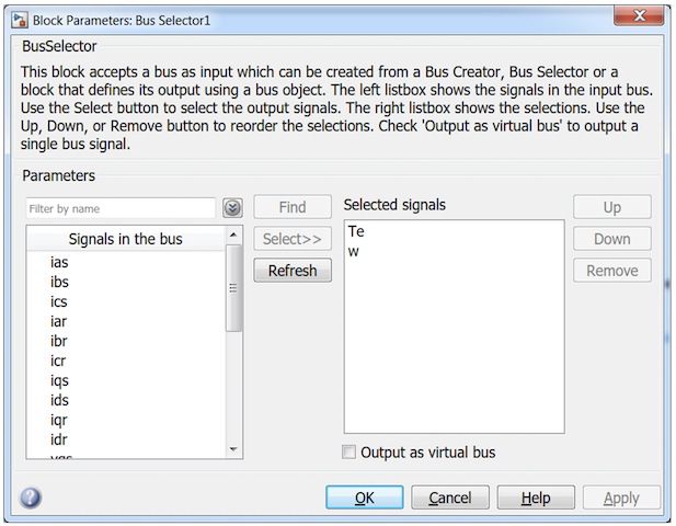
Bus Selector
Gain Block
Constant
Relational Operator
When the load of the motor increases, the rotor speed decreases. In reality, the rotor speed cannot be a negative. A Relational Operator block is used to stop the simulation when the rotor speed is equal or less than 0. The block’s input port 1 and 2 are connect to the rotor speed and the Constant block (with a value of 0), respectively. The relational operator is set to “<=” as shown in . The output value of the block is 0 if rotor speed is positive and 1 if the rotor speed is equal to or less than 0.
Stop Simulation
The simulation will stop when the input is nonzero. The input of the Stop block is connected to the output of the Relational Operator block. When the rotor speed is equal to or less than 0, the output value of the Relational Operator changes to 1, triggering the Stop block to halt the simulation.
PowerGUI
The PowerGUI block is an environment block for Simscape Electrical Specialized Power Systems blocks.
Complete The Model
Questions
- The machine used in these experiments has 4 poles (2 pole pairs) and the supply frequency is 50Hz. What is the synchronous speed in rpm?
- Set the load to zero in the Ramp block and run the simulation. Record the rotor speed.
Load Test
Questions
- Explain why the power factor improves as the machine is loaded.
- Explain how the machine is able to supply the torque required by the load.
Completion
Analysis/Discission
Comment upon your results and observation. Discuss the graphs obtained. Ensure all questions are answered.
Conclusion
Write a short conclusion based on the objective and what you have learned from the experiment.
Formal Report
The formal report should cover at least the following points:
- Introduction to induction machines, including relevant theory and a description of their operation.
- Results and graphs.
- Discussion of the results and graphs, with suggested reasons for any discrepancies with the theory. Include answers to the questions from the exercise.
- Sources of errors.
- Concise and relevant conclusions.
- References and appendices, if appropriate.