Control 1 - DC Motor Drive
Design of electronic circuit to vary motor speed
Introduction
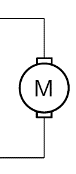
DC-motors may be used to drive rotating loads at different speeds by changing the DC voltage applied to the armature winding which lies on the rotor of a DC machine, using a variable DC power supply or the output of a power amplifier fed from a DC level, or slowly changing control signal. This allows low level electronics, e.g. a microcontroller, to control the speed of shafts or position of x-y stages and other mechanisms in applications, such as powered hand tools, office automation, machine tools and other production and placement machinery.
Driving a DC motor requires some form of linear or switch-mode power amplifier - known as the motor drive - because low-level analogue or digital electronic circuits cannot source or sink current above several mA without being overloaded, and this is not high enough to produce a useful driving torque in most practical applications.
The aim of the is lab is to apply material previously covered in circuit theory, electronic devices, power electronics, etc to design, build and test one or more DC-motor drive circuits using the power transistors, power MOSFETs, etc provided, and characterise operation experimentally. The circuits built and measurements made should be recorded during the lab to evidence skills attainment.
Objectives
To design and build a linear and switch-mode power amplifier to control the speed of a DC-motor from a low level, variable amplitude (or variable duty-cycle) control signal.
To build the circuits on a prototyping breadboard, energise it and measure the relationship between control signal level (or duty cycle) and speed, using the laboratory instrumentation provided.
Engineering skills
Experience will be gained in the following areas:
- Understanding the requirements and operation of a basic motor speed control system.
- Designing motor speed control circuits.
- Applying semiconductor devices.
- Constructing, operating, and testing prototype circuits.
- Using laboratory instrumentation to debug, test and characterise motor speed control systems.
- Documenting designs, explaining operation, measuring and recording performance.
Design
DC motor drive design based on linear amplifier
Sketch a circuit diagram of an op-amp voltage follower showing the power rails op-amp signals and power supply connections.

Modify the circuit by adding an input voltage source and a DC motor load. How may the circuit be used to control motor speed?
Explain any limitations of the circuit and why the circuit would be unlikely to work in practice.
Add a bipolar junction transistor to your circuit so that it still operates as a unity gain voltage follower and explain why this improves the circuit for driving DC motors.
To complete the circuit diagram so that it may be used for building and testing, add a 100 \(\Omega\) resistor between the input signal source and op-amp non-inverting input.
DC motor drive design based on a switch-mode amplifier
Sketch a circuit diagram of the power stage a DC/DC buck converter implemented with a power MOSFET.
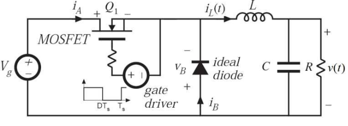
Redraw the circuit with the power MOSFET in a different position to show how the power MOSFET gate drive signal source may be referenced to the low-voltage side of the buck converter input voltage source.
Explain how the circuit may be controlled to vary the output DC voltage.
Add a DC motor to the modified buck converter and simplify the circuit by noting that a DC motor has internal inductance due to the armature winding, internal energy storage analogous to buck converter’s capacitance due to shaft, rotor and load inertia, and delivers output power (P = $\omega$ T) analogous to a buck converter output resistance.
To complete the circuit diagram that may be used for building and testing, add a 100 \(\Omega\) resistor between the gate drive signal source and the power MOSFET gate input.
Circuit construction
An attempt should be made to build and test both linear and switch-mode DC motor drive circuits; however, it may be quicker to build, test and measure the switch-mode DC-motor drive circuit first.
DC motor drive design using a switch-mode amplifier
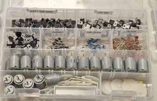
Component list, as shown below and listed after:
-
If available, use a prototyping breadboard with five rather than three or four 4mm terminal posts.
-
Small DC motor
-
Plastic gear wheel
-
100\(\Omega\) resistor
-
0.1\(\mu\)F capacitor
-
Power MOSFET, TO220 case
-
IN4000 series pn-junction diode
Using a BNC to 4mm terminal lead, attach the red and black of the waveform generator lead to the red and black breadboard posts. This will supply the variable duty cycle (aka duty ratio) power MOSFET gate drive signal.
First, connect the Com (or middle 0V) terminal of the power supply output to the black post of the breadboard, already connected to the 0V terminal of the waveform source. Second, connect the red +25V output of the power supply to the remaining unused breadboard 4mm post. Note, the +25V output should not be set above 10V.
Attach the DC motor to two 4mm breadboard anchor posts using 20cm lengths of wire so that the motor may be held above the work surface when making speed measurements.
Build the rest of your switch-mode amplifier circuit close to the 4mm terminals so that the waveform generator and DC motor may be easily connected using relatively short wires. Connect the 0.1 \(\mu\)F capacitor across the drain and source of the MOSFET to reduce switching noise.
Circuit operation
DC motor drive using a switch-mode amplifier
Turn on the waveform generator and set the output to a 50% duty cycle, ±10V, 5kHz signal.
Turn on the power supply and slowly increase the +25V output to 9V.
The motor should now be rotating at a relatively fast speed. Make sure that the circuit is operating correctly and that the speed varies with voltage down to zero or a low speed.
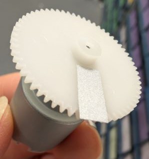
To measure speed using the non-contact, optical tachometer, fix the plastic gear wheel, as shown below, firmly and squarely to the DC motor shaft and attach a piece of reflective tape to the flat gear wheel surface to give one bright reflection of the laser spot per shaft revolution.
Results 1: Set the power supply voltage to 9V and change the duty cycle of the waveform generator output, if possible, from 0% to 100%, in 10% steps, otherwise 10% to 90% in 10% steps.
Measure and record the motor speed using the non-contact, optical tachometer. The results can be plotted later in Excel, but even at this stage you should note how motor speed varies with the duty cycle of the control signal, e.g linear or otherwise.
| Duty Cycle (%) | Motor speed (RPM) |
| 0 | |
| 10 | |
| 20 | |
| 30 | |
| 40 | |
| 50 | |
| 60 | |
| 70 | |
| 80 | |
| 90 | |
| 100 |
Results 2: Repeat the measurement at a fixed duty cycle of 50%, for different supply voltage levels of 9, 8, 7, etc. This can be considered in more detail later, but at this stage note why is this likely to be a problem in DC motor drives and how it might be overcome.
| DC supply voltage (V) | Motor speed (RPM) |
| 9 | |
| 8 | |
| 7 | |
| 6 | |
| 5 | |
| 4 | |
| 3 |
Circuit construction
DC motor drive design using a linear amplifier
Component list:
-
If available, use a prototyping breadboard with five rather than three or four 4mm terminal posts.
-
Small DC motor
-
Plastic gear wheel
-
Piece of reflective material for speed measurement using optical tachometer
-
100 \(\Omega\) resistor
-
Power transistor, TO220 case (actually Darlington configuration, hence 2 transistors in cascade inside)
-
Power MOSFET in T220 case
-
741 op-amp
-
1N4001 diode
-
0.1 \(\mu\)F ceramic disc capacitor
Disconnect the BNC to 4mm terminal lead connecting the waveform generator to the breadboard.
As previously, connect the Com (or middle 0V) terminal of the power supply output to the black post of the breadboard.
Connect the red +25V output of the power supply to the red breadboard 4mm post. Note, the +25V output should not be set above 10V. Connect the -25V output of the power supply to an unused adjacent 4mm breadboard post. Note, the -25V output should not be set below -10V. You now have +ve, 0V and -ve supply rails available to power the circuit.
The +6V power supply output may be used to create a variable DC signal to vary motor speed via the linear amplifier but must be referenced to the other power supply output 0V or Com terminal to do this.
Connect the +6V power supply output to a spare breadboard 4mm terminal post and the black or low-voltage side of the +6V power supply output to the black 4mm breadboard terminal post, so that the +6V level is reference to the +25V output 0V level.
Attach the DC motor to two 4mm breadboard posts using 20cm of thin multistrand wire wound round motor terminals so that it may be raised above the work surface if required when making speed measurements.
Build the rest of your linear amplifier drive circuit close to the 4mm terminals so that the waveform generator and DC motor may be easily connected using relatively short wires.
To measure speed using the non-contact, optical tachometer, fix the plastic gear wheel firmly and squarely to the DC motor shaft and attach a piece of reflective tape to the flat gear wheel surface to give one bright reflection of the laser spot per shaft revolution.
Results 3: Set the power supply voltage to 6V and change the level of the control 6V power supply output in steps of 1V from 0V to 6V.
Measure and record the motor speed using the non-contact, optical tachometer. The results can be plotted later in Excel, but even at this stage you should note how motor speed varies with the duty cycle of the control signal, e.g linear or otherwise.
| 6V output voltage (V) | Motor speed (RPM) |
| 0 | |
| 1 | |
| 2 | |
| 3 | |
| 4 | |
| 5 | |
| 6 |
Results 4: Repeat the measurement at a fixed control voltage of 4.5V with different supply voltage levels of 9, 7, 6, etc. This can be considered in more detail later, but at this stage note why this is likely to a problem in DC motor drives and how it might be overcome.
| DC supply voltage (V) | Motor speed (RPM) |
| 9 | |
| 8 | |
| 7 | |
| 6 | |
| 5 | |
| 4 | |
| 3 |
Conclusion: Compare both amplifier designs. Without mentioning cost or complexity, discuss two advantages and two disadvantages of the switch-mode amplifier based motor drive. Discuss two advantages and two disadvantages of the linear amplifier based motor drive.
Discuss which aspects of motor drive performance are particularly important when designing motor drives for electric vehicles. Explain how these would affect your chosen motor drive system design.
Equipment and component list
Equipment per workstation in addition to standard lab workstation instrumentation:
-
Four or five 4mm-post breadboard preferred. Use three 4mm-post breadboard if no alternative.
-
Box of wires or small pair of wire strippers so groups can form leads from 0.5m of single core wire.
-
Non-contact optical tacho when ready to measure speed since those are to be shared.
-
10mm length of reflective tape for non-contact tacho when ready to measure speed.
-
Op-amp tester which are to be shared. Test the op-amp before to using them.
Components per workstation:
-
Small DC motor specifically obtained for this lab
-
Plastic gear wheel
-
741 op-amp
-
TIP120 Darlington power transistor (or equivalent)
-
IRF1010 Power MOSFET (or equivalent >20V>2A)
-
1N4000 series diode, e.g. 1N40001 or higher last digit
-
100 \(\Omega\) axial 1/8W or 1/4W resistor
-
0.1 \(\mu\)F ceramic disc capacitor