Pulse Oximetry Kit
Pulse Oximetry can be done using simple analogue or more complex digital components. We have provided you with the building blocks for a PCB based digital system to do just that. We have also provided basic analogue components for you to create an analogue system which can read heart rate and SpO2 values on the Arduino.
Each group of students will receive a kit including:
| Description | Part Identifier | Qty per Kit |
|---|---|---|
| Click boards™ Arduino Shield | - | 1 |
| Heart Rate Click (MIKROE-2000) | U3 | 1 |
| Midas 96*16 OLED Display | JP2 | 1 |
| Tactile Switch (SPDT) | S1, S2 | 2 |
| Slide Switch (SPDT) | S3 | 1 |
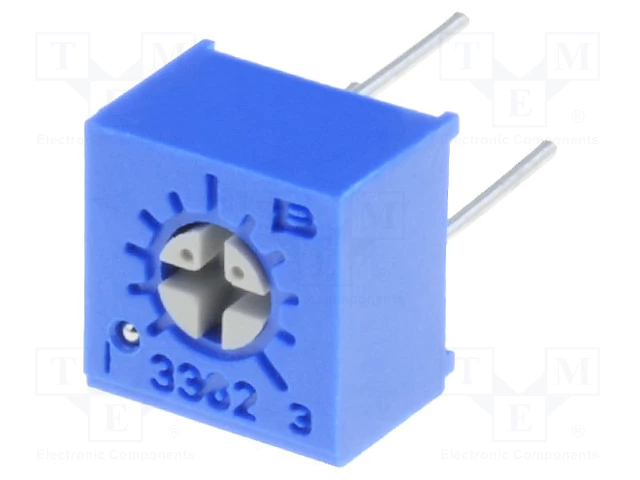
| Potentiometer (250 Ω) | VR1 | 1 |
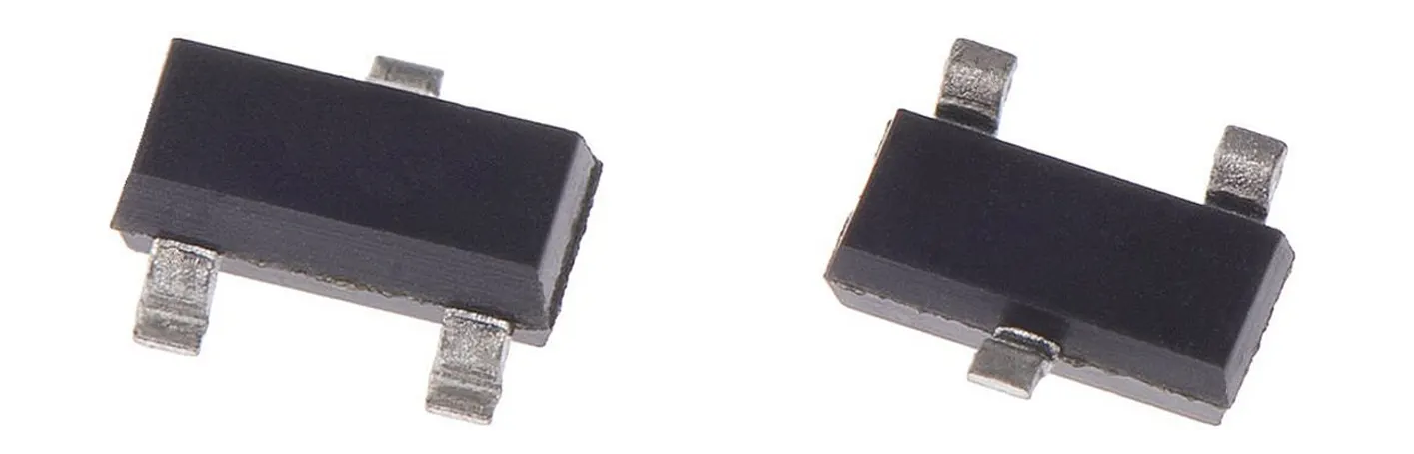
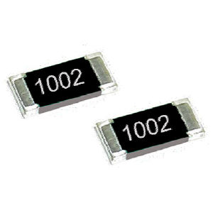
| SMD Resistor (10 kΩ) | R4, R5 | 2 |
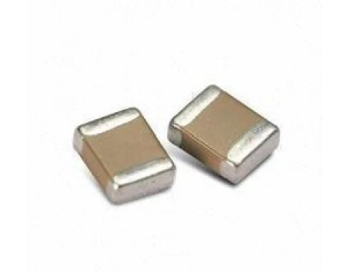
| SMD Capacitor (0.1 µF) | C1, C2 | 2 |
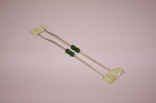
| THD Resistor (75 Ω) | R1, R2 | 2 |
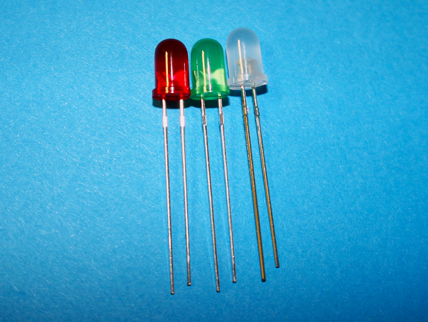
| Red LED (5mm) | D1 | 1 |
| Green LED (5mm) | D2 | 1 |
| Red & Green Bipolar LED (5mm) | D3 | 1 |
| 5V LDO Voltage Regulator** | U1 | 1 |
| 8-Pin Socket | For U3 | 2 |
| 22-Pin Socket | For U2, JP2, and JP3 | 2 |
| Phototransistor Diode | - | 1 |
| IR Emitter Diode | - | 1 |
| TL071 Operational Amplifier | - | 1 |
| 3.3 V Zener Diode | - | 1 |
| THD Resistor (220 Ω) | - | 1 |
| Wooden Spacer | - | 1 |
| Glue Dots | - | 2 |
Components for the Dual-Wavelength System
The following components will be used to build the Digital Pulse Oximeter prototype. Links to the datasheets of the various components are provided to assist with understanding the system, its design, and its limitations.
Click boards™ Arduino Shield
Click boards, also known as mikroBUS™ Click boards, are a type of modular extension board standard developed by MikroElektronika. These boards are designed to be compatible with the mikroBUS™ socket, which is a standardized socket found on many development platforms, including various microcontroller and development board ecosystems.
This shield PCB was designed to give the Arduino Nano ESP32 access to the full range of Click boards™ modules while providing the user with access to useful inputs and outputs.
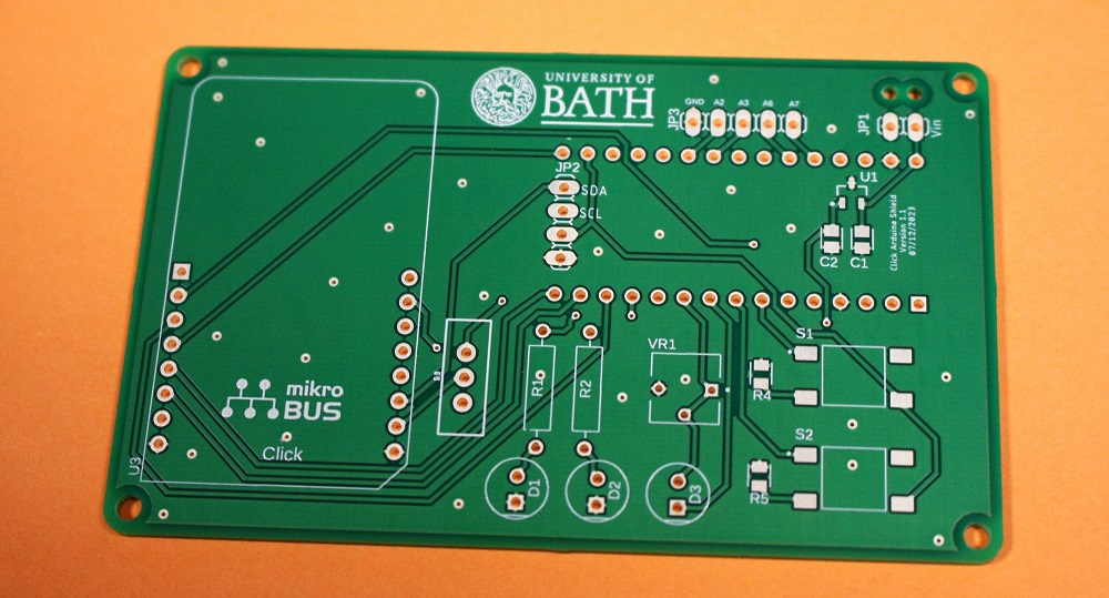
The Schematic of the design can be seen in and will help with populating the board later on.

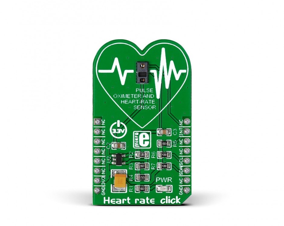
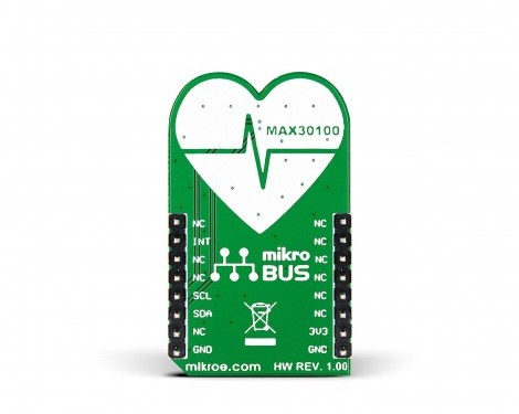
Heart Rate Click
Heart Rate click is a heart rate monitoring and pulse oximetry measuring Click board™. It features an advanced oximeter and heart rate monitoring sensor, which relies on two integrated LEDs, a photosensitive element, and a very accurate and advanced low noise analog front end, to provide clean and accurate readings.
The Heart Rate click features the MAX30100 sensor IC from Analog Devices.
Datasheets:
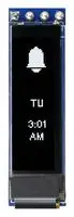
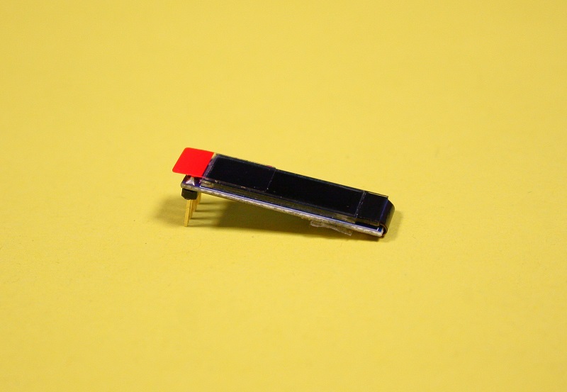
OLED Display
This organic light-emitting diode (OLED) display, with a resolution of 96 pixels in width and 16 pixels in height, is suitable for applications such as wearable devices, small electronic gadgets, or projects with space constraints.
Datasheet:
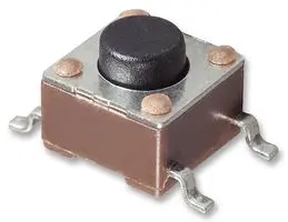
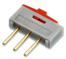
Switches
These tactile switches are used as inputs to the arduino system. Use the system schematic to identify the Arduino pins to which these are assigned.
The slide switch is used to shift from the 5V provided by the Arduino when powered by USB to that of the regulated supply from a 9V battery. This should not be needed for this project but is necessary for other projects you may want to attempt with this system.
Datasheets:
Voltage Regulator
This will prevent damage of the Click board™ when the system is powered by a battery. This is a 5V low dropout (LDO) linear regulator designed to provide a stable output voltage with low dropout voltage, making it suitable for applications where a regulated output is required, and the input voltage may be close to the desired output voltage. This will prevent damage of the Click board when the system is powered by a battery.
Datasheet:
Light Emitting Diodes (LEDs)
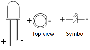
Three LEDs are provided with the system: Red, Green and a Bipolar (Red & Green). These can be used to provide a visual output from the system.
Datasheets:
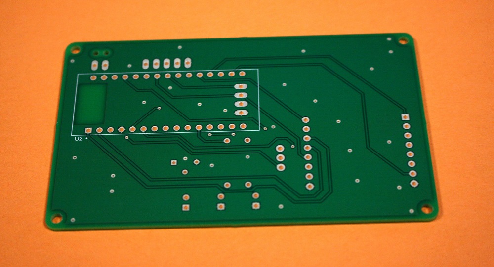
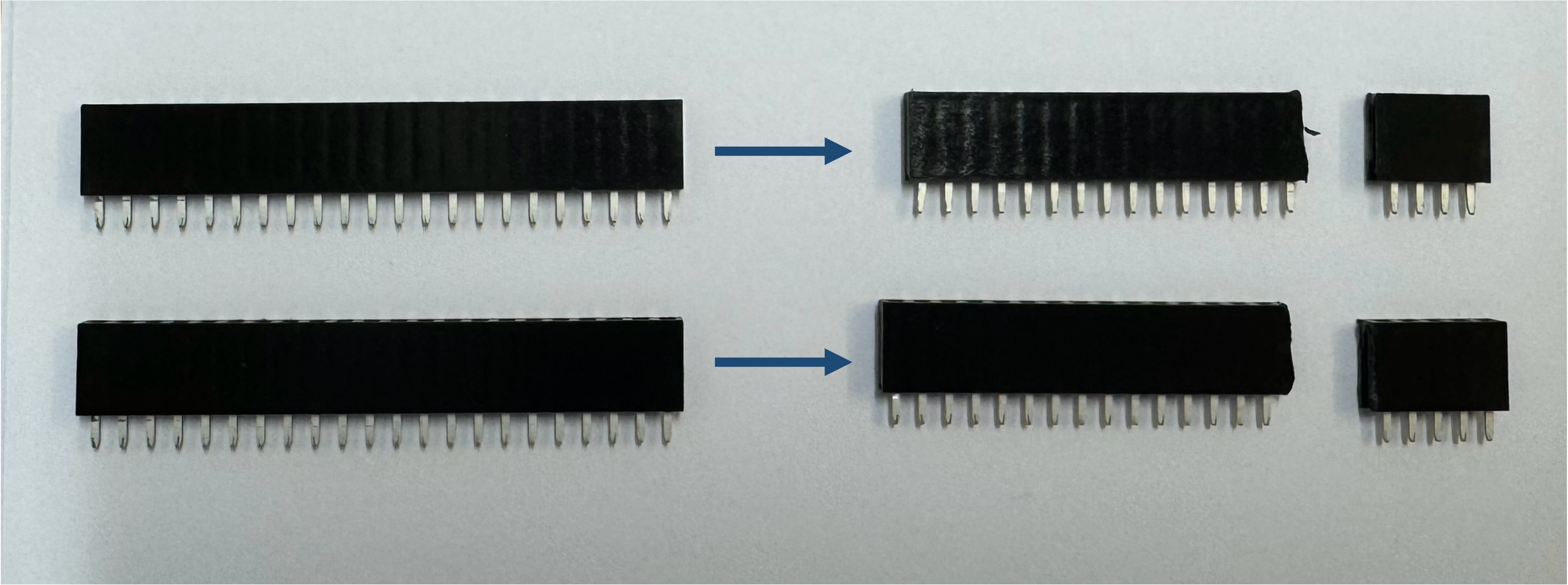
Sockets
To allow the replacement and return of components, PCB Sockets are to be used to connect the Arduino, Heart Rate Click, and OLED screen. These sockets will also be used to provide access to the remaining analogue pins and GND point on the PCB.
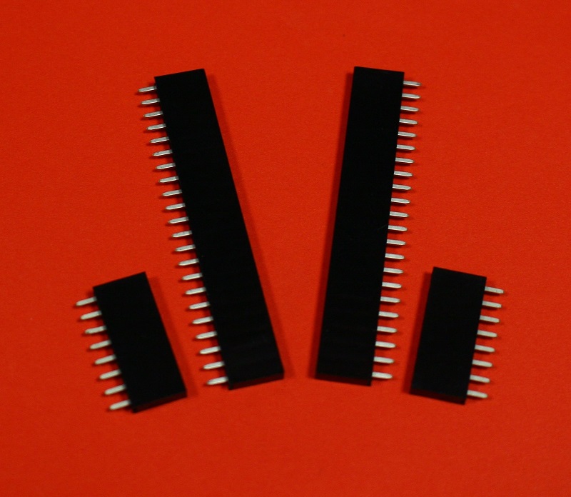
- The 2x 8-pin sockets should be used for the Heart Rate Click (U2) pins.
- The 2x 22-pin sockets must be split as shown below to form 2x 15-pin sockets for the Arduino (U1) pins, 1x 4-pin socket for the OLED screen (JP2) pins, and 1x 5-pin socket for the JP3 pins. Use wire cutters to carefully split the 22-pin sockets as illustrated, taking care not to damage more than one pin in the process.
Passive Components
The following components are required for the correct operation of the system:
- Pull-down Resistor for tactile switches. Connects the switch to GND. When the switch is open, the resistor pulls the input signal low.
- Decoupling Capacitors for voltage regulation. They are used in electronic circuits to stabilize the power supply voltage and reduce the effects of electrical noise.
- Current limiting Resistors to limit the current flowing through the LEDs and protect them from damage.
Components for the Single-Wavelength System
Phototransistor Diode
A phototransistor is a type of semiconductor device that can be used to detect light and convert it into an electrical signal. It operates on the principle of the photoelectric effect, where incident light generates electron-hole pairs in the semiconductor material, causing a change in the transistor’s conductivity. They are commonly used in various applications, such as optical communication, proximity sensing, ambient light detection, and automation. They are often used in conjunction with infrared (IR) or visible light-emitting diodes (LEDs).

Datasheet:
IR Emitting Diode
IR LEDs emit infrared light, which is not visible to the human eye but can be detected by electronic devices. he specific wavelength range can vary, but it is generally between 700 nanometers (nm) and 1 millimeter (mm). These LEDs are commonly used in various applications, including remote controls, proximity sensors, security systems, and communication systems.

Datasheet:
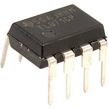
TL071 Operational Amplifier
The TL071 is a low-noise JFET-input operational amplifier (op-amp) that is widely used in electronic circuits. It is a part of the TL07x series of op-amps produced by various manufacturers. The TL071 is known for its high input impedance, low input bias current, and low offset voltage, making it suitable for applications where precision and low noise are important.
Datasheet:
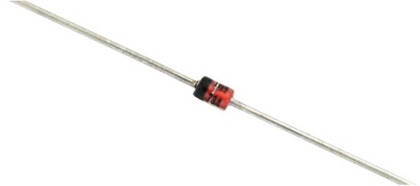
3.3 V Zener Diode
A Zener diode is a type of diode designed to allow current to flow in the forward direction like a normal diode, but also in the reverse direction when the voltage is above a certain value known as the breakdown voltage.
Datasheet:
Additional Components
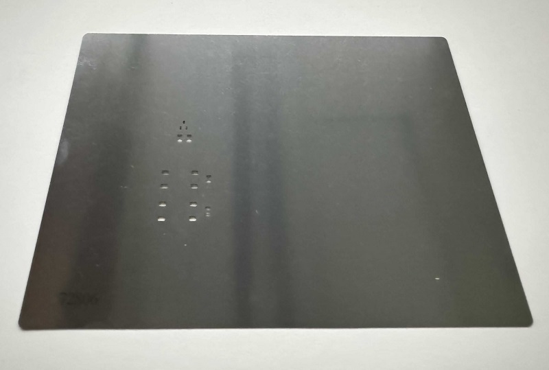
PCB Stencil
Using a PCB stencil improves the accuracy and efficiency of the solder paste application process, reducing the likelihood of defects and ensuring consistent solder joints.
Spacer
Used with OLED suspended in socket to prevent damage.

Glue Dots
Used with OLED suspended in socket to prevent damage.
Breadboard
For the duration of the project week, please use the breadboard supplied with your Robotics kit.
More Passive Components
For additional components that you may need to design your analogue circuit, speak with a Lab Technician for the size of component you require.