Wind Turbine Kit
The wind turbine is composed of two different sets of components:
- The mechanical components
- The electronic components
Each group of students will receive a kit including:
| Description | Qty Per Kit |
|---|---|
| Front face plate | 1 |
| Rear face plate | 1 |
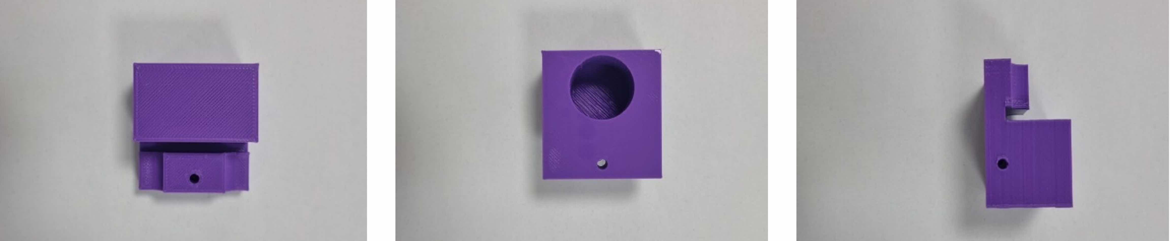
| Mounting block | 1 |
| Orange 917D/2 gear mounted on 80mm threaded axle | 1 |
| Orange 917D/2 gear mounted on 40mm axle (no thread) | 1 |
| Green 917D/2 gear | 1 |
| 40 mm axle (no thread) | |
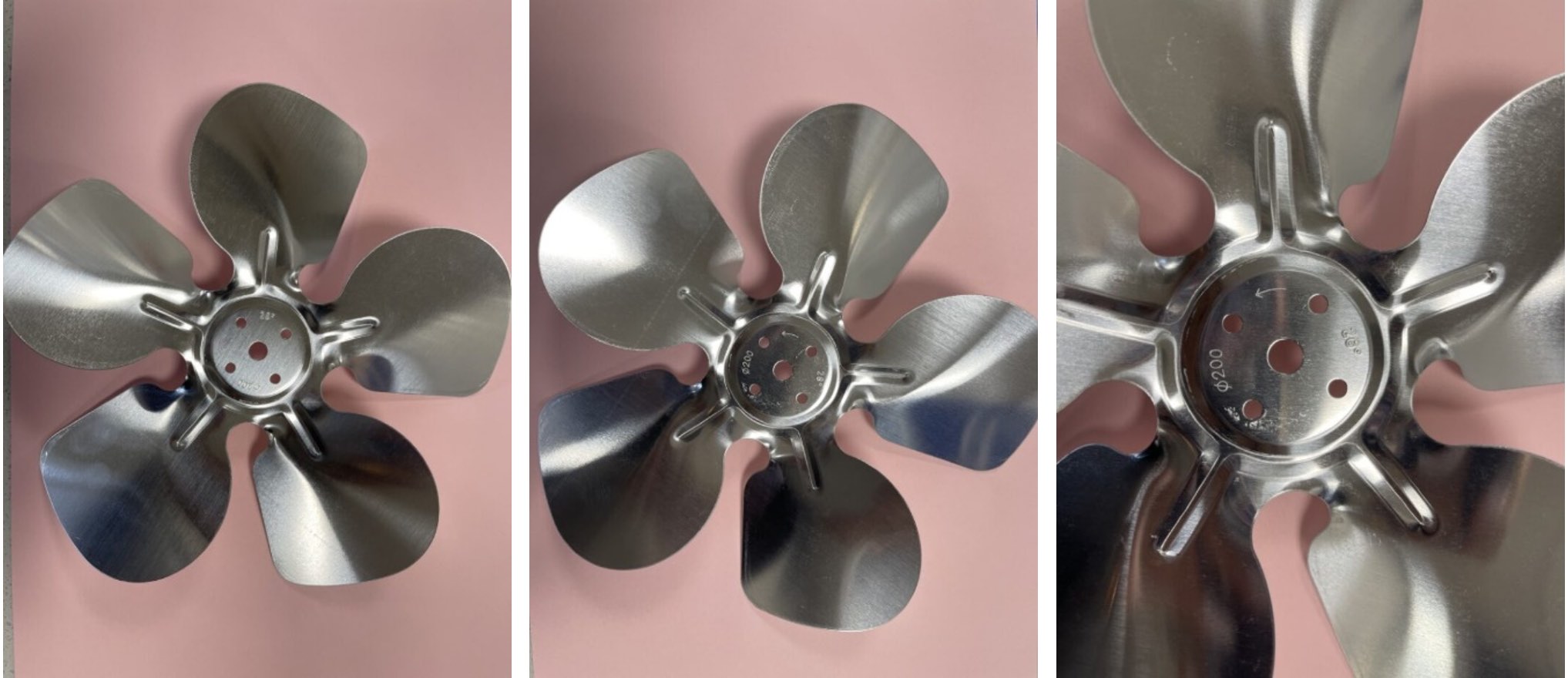
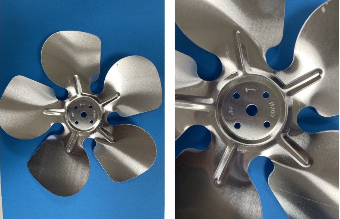
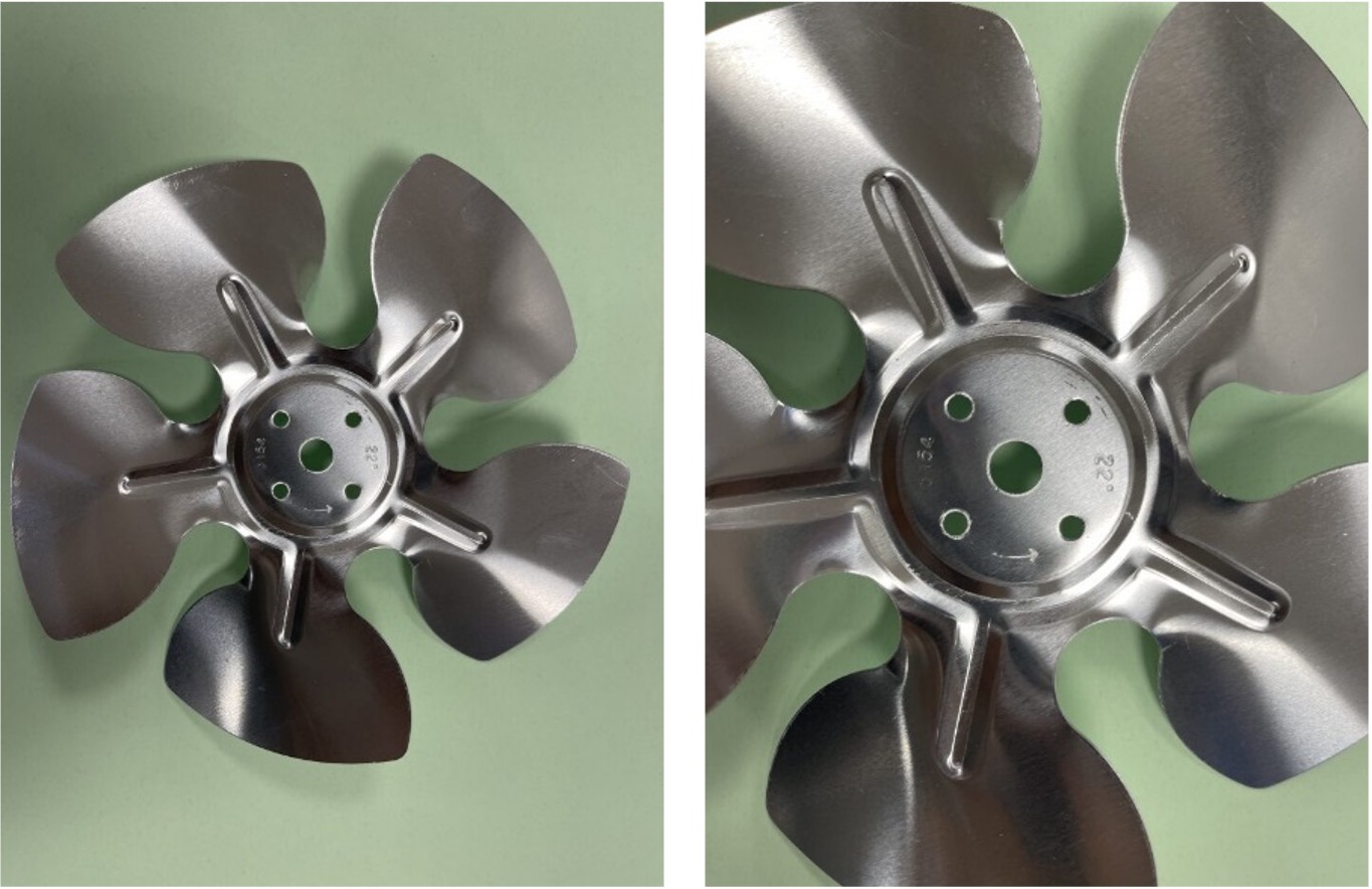
| 200 mm 28° fan blade | 1 |
| 200 mm 22° fan blade | 1 |
| 154 mm 22° fan blade | 1 |
| M4 x6 screw | 4 |
| M4 x40 screw | 2 |
| M3 x20 screw | 1 |
| M3 x10 screw | 4 |
| M3 x15 screws | 2 |
| M3 nut | 7 |
| M4 nut | 2 |
| M4 washers | 4 |
| M4 stand offs | 2 |
| Push on clip | 8 |
| Shoulder washer | 4 |
| Pipe clip | 1 |
| Motors | 3 |
| Acrylic cross | 2 |
| Acrylic mast pipe | 1 |
| 47 kohm resistor | 1 |
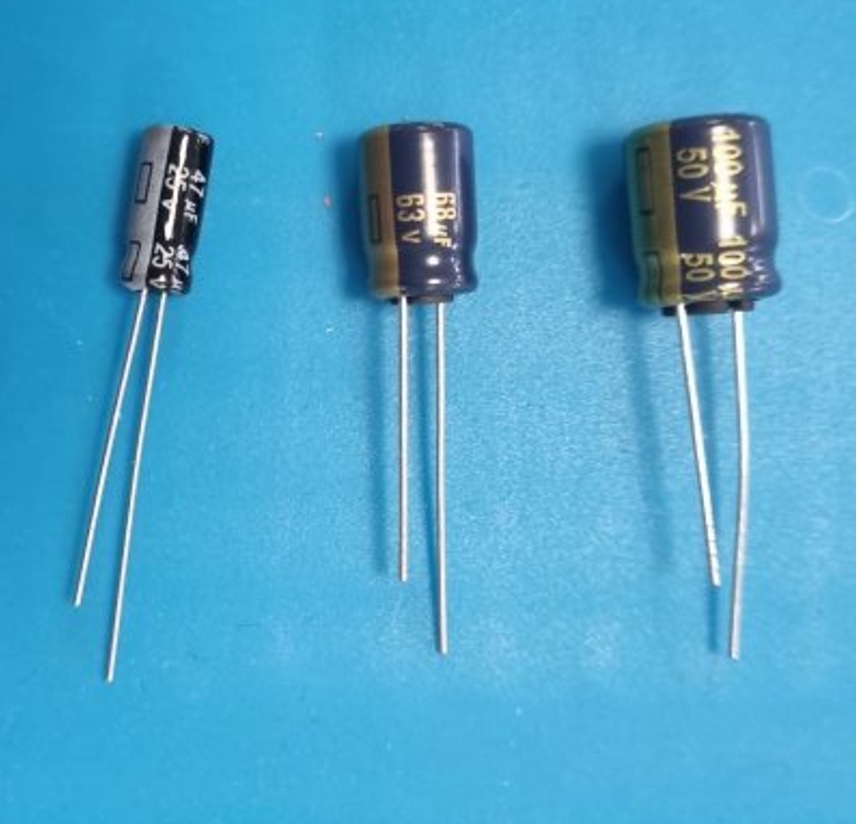
| 47 uF capacitor | 1 |
| 68 uF capacitor | 1 |
| 100 uF capacitor | 1 |
| Plier | 1 |
| Screwdriver | 1 |
| Allen key | 1 |
The Mechanical Components
The aim of those components is to transform the wind into rotational motion.
Blades
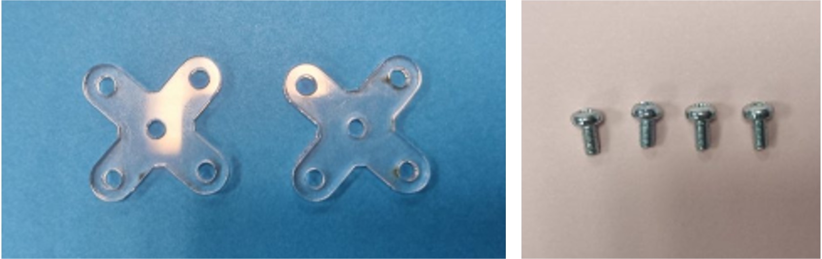
Blade Mounting Plates
Mounting plates are used to enable it to be mounted on the roles. Four M4 screws are used to hold the mounting plates on either sides of the blade.
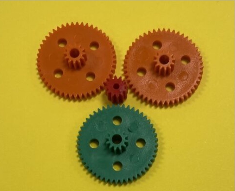
Gear Set
Gears in wind turbines enable the conversion of a low-speed, high-torque input to a high-speed, low-torque output, which is optimal for the generator to produce electricity efficiently.
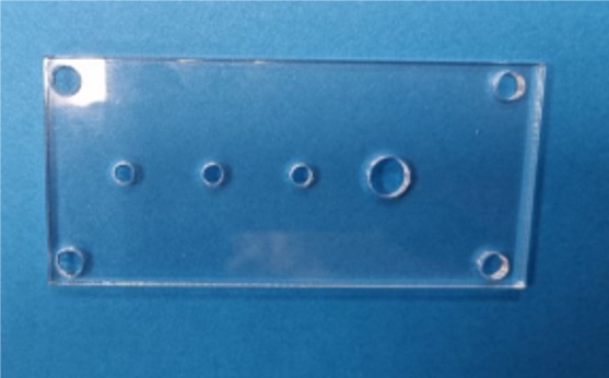
Face Plates
The face plates hold the axels (see below) and motor. There should be 2x face plates; a front face plate (fan-side face plate) and a rear face plate (motor-side face plate).
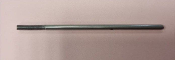
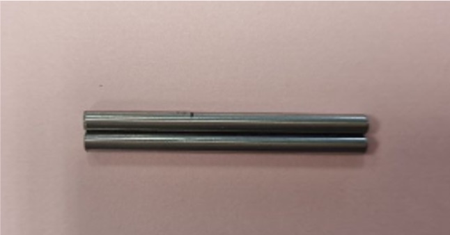
Axels
The axels are used to hold the gears and blades.
The mast
The mast serves as a robust framework, providing a secure mounting point for the motor and other essential components like faceplates. It ensures that the motor and faceplates are firmly anchored and positioned correctly, facilitating the smooth operation of the turbine by holding the rods and motor in place.
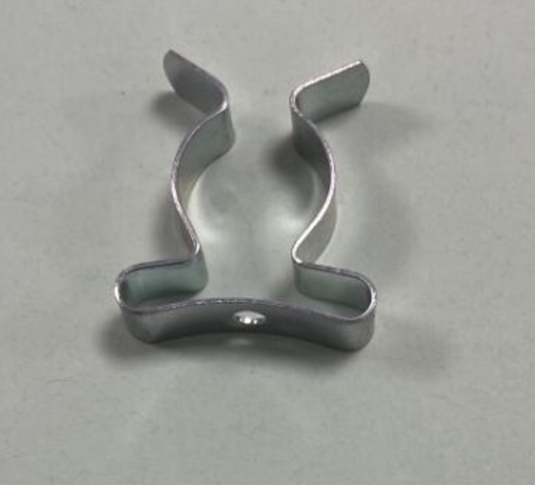
Pipe Clip
The pipe clip is used to affix the motor to the mounting block and face plate.
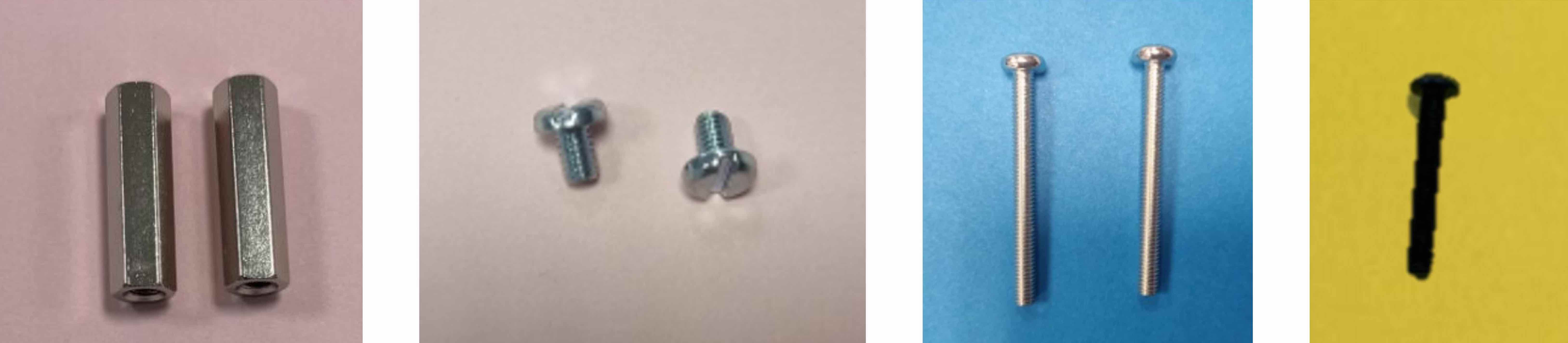
Fastners
Below is the variety of fastners and components used to affix the components.
- Hexagonal connector nuts (M4 x25 standoff) are used to set the face plates’ distance and hold the structure together.
- Pan head screws are used to affix the faceplate to the standoffs
- Hex socket screws are used to hold the mounting block to the face plates
- Push-on fasteners are used for the ends of all the axles.
- M4 washers are used with the M4 screws for holding the block to the plate.
- Pipe clips are used to secure the green gear in place.
- The M4 nuts are used to hold the face plates to the mounting block
- 4 M3 nuts are used for the corners of the blade mounting plate and 3 M3 nuts are used to secure the blade in place on the axel (one behind the blade and 2 in front of it)
The Electrical Components
The aim of the electrical components is to transform the mechanical rotation to a DC electrical signal.
The Generators
You are provided with three different brushed DC motors that can be used as generators.
- GENERATOR 1 (PEL00882): 18000 rpm, 11.6 g-cm, 420 mW BDC motor
- GENERATOR 2 (PEL00881): 14700 rpm, 14.1 g-cm, 1650 mW BDC motor
- GENERATOR 3 (MM18): 4300 rpm 15.5 g-cm, 420 mW BDC motor
Motor Basics:
- A brushed DC motor consists of a rotating armature wound with coils, stationary magnets, and a commutator with brushes.
- When powered, the stationary magnets create a magnetic field, which interacts with the magnetic field generated by the current flowing through the armature. This interaction generates a torque that causes the armature to rotate.
Energy Harvesting:
- Energy harvesting involves utilising the motor in a generator mode.
- When an external mechanical force spins the motor’s shaft, the armature coils move through the magnetic field, inducing a voltage (Faraday’s Law of electromagnetic induction). This voltage can be harvested and used as a power source.
The datasheets for the different motors/generators can be downloaded using the links below.
The load
A $47 k\Omega$ resistor will be used to help in limiting the current.
The Capacitors
You are given three different capacitors to choose from. A capacitor stores energy and releases it to smooth out the fluctuations in the voltage.