Restrictor Calculator for Multi-Patient Ventilation
IMPORTANT: Attaching two patients to a single ventilator is not recommended. Use the information below with discretion.
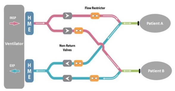
This tool guides the selection of ventilator settings and flow restrictors for two patients on a single ventilator. Given the tidal volume and end expiratory pressure requirements for each patient, it guides selection of appropriate ventilator settings and then computes the corresponding resistances to be added to the inspiratory and expiratory circuits. The resulting pressure, flow, and volume responses are plotted against time at the bottom. Click the "info" links in the top right corner of any box for detailed guidance on that step.
This tool guides the selection of ventilator settings and flow restrictors for two patients on a single ventilator. Given the tidal volume and end expiratory pressure requirements for each patient, it guides selection of appropriate ventilator settings and then computes the corresponding resistances to be added to the inspiratory and expiratory circuits. The resulting pressure, flow, and volume responses are plotted against time at the bottom. Click the "info" links in the top right corner of any box for detailed guidance on that step.
Further information:
- For more notes on how to use this tool, see these instructions (PDF version).
- For more detail on the computations behind the tool, see our paper and the orignal source code (including original MATLAB and Excel versions of this page).
BathRC-web v1.2 © University of Bath 2020; based on this paper and this dataset
More information on differential multiventilation (the method this tool supports) at differentialmultivent.org
More information on differential multiventilation (the method this tool supports) at differentialmultivent.org
Ventilator Settings and Restrictor Requirements
Info
- These figures are generated according to the parameters entered above.
- In figure 1 the x- and y-axes represent, respectively, the ventilator pressure and duration for the inspiration phase.
- In figure 2 the x- and y-axes represent, respectively, the ventilator pressure and duration for the expiration phase.
- The contours on the two graphs show the restrictor coefficients required for each patient on the inspiration circuit (Fig 1) and expiration circuit (Fig 2) in order to meet their respective tidal volume and end expiratory pressure requirements.
- The green indicator dots are positioned by changing the values in the boxes beneath the figures or by clicking on the figures themselves, to select the desired ventilator settings.
- The resulting restrictor resistance requirements are displayed in the red and blue boxes beneath. Four restrictors need to be added, one to each of the individual inspiratory and expiratory circuits for each of the two patients.
- The "ventilation response" section of the page shows graphs of the pressure, flow, and volume for each patient against time for this configuration.
- Summary information appears at the bottom of the page.
Ventilation response
Summary
Info
- Patient tidal volume and lung end expiration pressure requirements as entered at the top of this form.
- Ventilator settings, calculated from the values chosen beneath Figs. 1 and 2.
- Restrictor resistances, computed to meet the requirements of (I) and (II).
I. Patient tidal volume / lung end expiration pressure requirements
II. Ventilator settings
III. Restrictor resistances