Dual Patient Ventilation: Restrictor selection using Bath RC model
V2 ARP 25/4/2020. © University of Bath
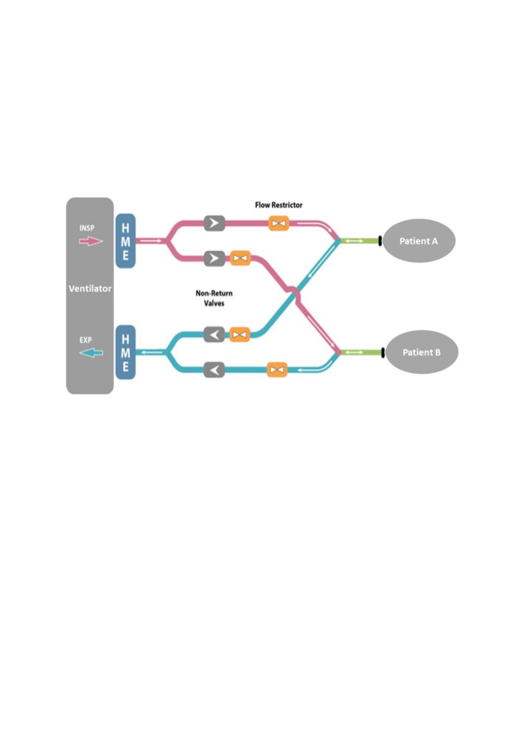
We assume there is a (linear) flow restrictor in each line, adjustable from zero resistance upwards.
‘RC_restrictor_curves.m’ displays the full range of possible resistances which will give a specified
tidal volume and PEEP for each patient, plotting against ventilator settings (Pinsp, PEEP, and
inspiration and expiration time durations).
Example parameters:
Ventilator tubing parameters
vent.R
= 22;
% cmH2O/(L/s)
vent.C
= 0.004;
% L/cmH2O
Patient 1 (‘compliant’)
pat(i).Ri
= 12;
% cmH2O/(L/s) Inspiration airway resistance
pat(i).Re
= 12;
% cmH2O/(L/s) Expiration airway resistance
pat(i).C
= 0.040;
% L/cmH2O
Lung compliance
Patient 2 (‘stiff’)
pat(i).Ri
= 10;
% cmH2O/(L/s) Inspiration airway resistance*
pat(i).Re
= 10;
% cmH2O/(L/s) Expiration airway resistance*
pat(i).C
= 0.020;
% L/cmH2O
Lung compliance
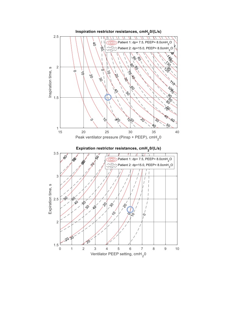
Say we want both patients to have a tidal volume of 0.3L, and a PEEP of 8cmH20 (taken as minimum
lung pressure, so not including any pressure drop through airway due to remaining flow at the end
of expiration). The required lung pressure change (dp) for Patient 2 is double that for Patient 1 due
to increase stiffness.
The full combination of inspiration time period, pressure and restrictions is given in the first figure,
and the full combination of expiration time period, pressure and restrictions is given in the second
figure.