Arithmetic Logic Unit
Introduction
You will develop the Arithmetic Logic Unit (ALU) for your HighRisc processor, which will implement the ISA defined in the document “EE20021 - HighRisc processor instruction set architecture”. You will implement only instructions 3 to 15 (see opcodes) described in the ISA. To get started, download the zip file for this activity from Moodle, where you will find the following files:
- ArithmeticLogicUnit.sv – A template of the ALU module. The instructions ROL and NAND have been already implemented for you as an example. You will need to implement the rest of the instructions from 3 to 15 (see opcodes).
- InstructionSet.sv – A package that defines opcodes, flags and constants. Set DataWidth in this file to 4 when implementing on the FPGA and to a value of 16 for simulation.
- AluTb.sv – A template testbench that allows the simulation of the ALU operations in Questa. This is pre-configured with a test for the NAND, ADC and LIU operations.
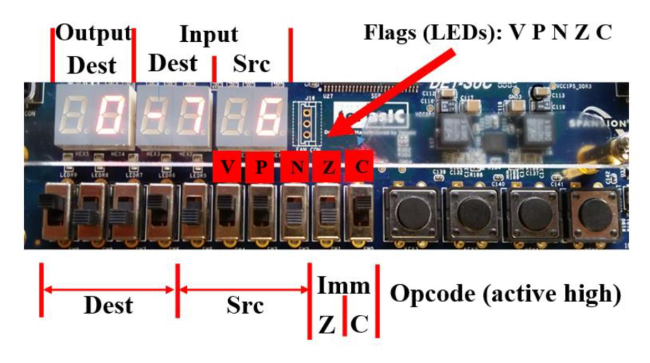
- AluFpgaTop.sv – A module called AluFpgaTop that instantiates the ALU and connects the inputs and outputs of the DE1-SoC as shown in figure 1. This file is NOT used in simulation.
- soc_system.qsf – An assignments file that allows you to connect the ports in AluFpgaTop to the physical switches and LEDs on the DE1-SoC.
- EE20021 - HighRisc processor - instruction set architecture.pdf – Description of the instructions that will be executed by the HighRisc processor.
Activity 1 – Verify NAND
Start Questa and compile InstructionSet.sv, ArithmeticLogicUnit.sv and AluTb.sv in that order. Simulate AluTb and observe the NAND operation test. Add additional lines to the initial block in AluTb.sv to test the ROL instructions.
Activity 2 – Hardware testing
Create a Quartus project called ArithmeticLogicUnit and when you get to the Add Existing Files window of the project wizard, add InstructionSet.sv, ArithmeticLogicUnit.sv and AluFpgaTop.sv.
Edit InstructionSet.sv to make the DataWidth parameter 4 when testing in hardware. Set DataWidth to 16 when testing in simulation. Import the pin assignments from the soc_system.qsf and compile the design.
Activity 3 – Make it better
Add additional instructions and implement the logic for the flags. Simulate your instructions and don’t forget to set the DataWidth to 16 for simulation and 4 for implementation on the FPGA. It is recommended to add one instruction at a time and verify it in simulation.
Tips for Self-evaluation of the ALU
- “I tried a new instruction but it didn’t work”. You are on the edge: Check the errors from the simulation (check the error line) and try to solve them.
- “I got one new instruction working”. You are surviving; Try to find the time to extend this work to more instructions or flags.
- “I got some new instructions of different types and most of the flags working”. You are doing well. Keep up the good work.
- “I got all of the instructions and flags working” well done! You are a SystemVerilog Ninja!