Electronic Lock with State Machines
In this tutorial you will create a programmable electronic lock.
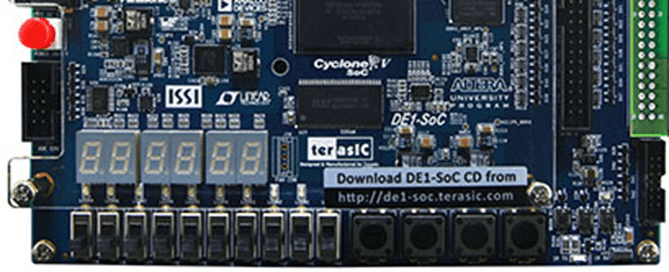
The lock has a four-digit key which is entered using the four push buttons on the FPGA.
If the push buttons are pressed in the right sequence the 7 segment displays will change from CLOSED to OPEN when the fourth key is entered correctly.
On the next key press, the display will change back to CLOSED. If the wrong button is pressed at any point, the lock should clear back to its initial state.
The key sequence to open the lock is defined using the switches SW[7:0], where SW[1:0] sets the first digit of the key (e.g., 0, 1, 2 or 3), SW[3:2] sets the second digit, SW[5:4] sets the third digit and SW[7:6] sets the fourth digit. Use the switch SW[9] to reset the sequence at any point.
The clock for the module should be called CLOCK_50.
Activity A: State Machine
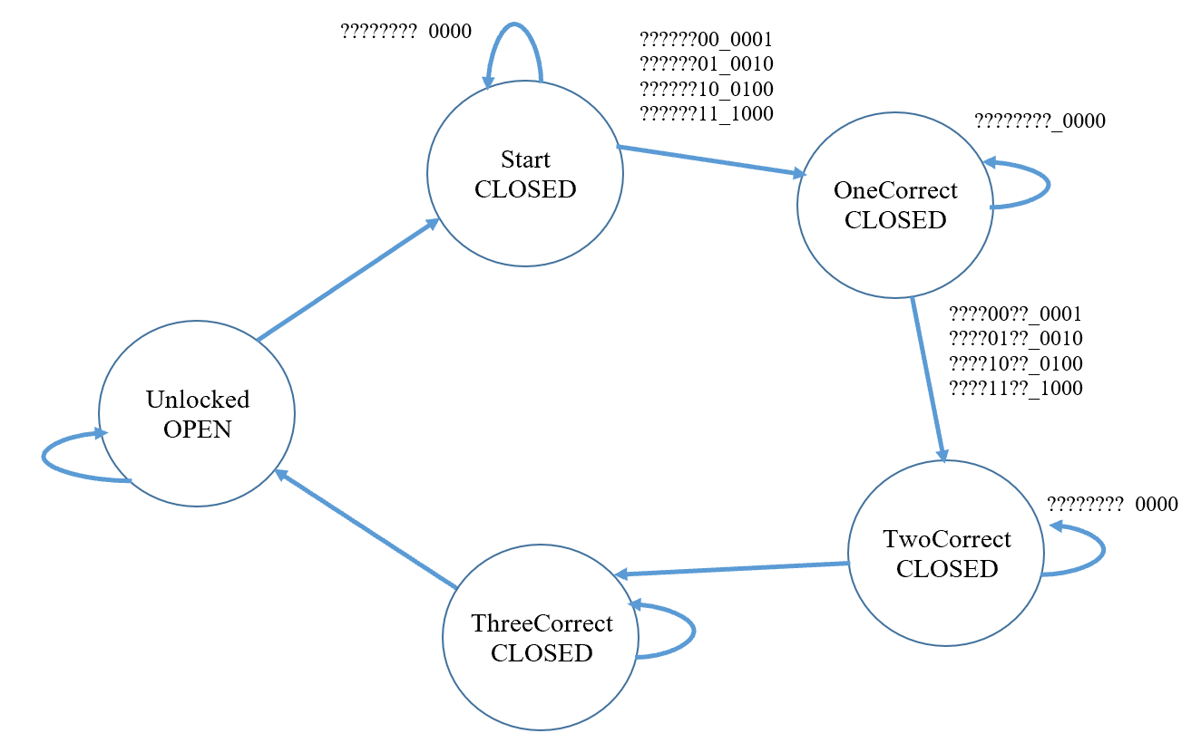
Complete the state machine diagram below.
Inputs:
SW[9]: resets the state machineSW[7:0]: defines the correct key sequence to open the lockKEY[3:0]: used by the user to enter the key sequence
Outputs:
- Text using the seven segment displays
States of the FSM:
- Start
- OneCorrect
- TwoCorrect
- ThreeCorrect
- Unlocked
Activity B: Simulation
Create a state machine module and a testbench to test it. Look through the simulation waveform and make sure that the function is correct.
Activity C: Implementation in the FPGA
Add combinatorial logic to create the words OPEN and CLOSED on the seven segment LEDs according to the output from the state machine. Use the outpus signal from the slow clock module that has been provided in this tutorial to update the finite state machine. This slow clock module receives CLOCK_50 as input signal and outputs a low frequency pulse. Implement the state machine on the FPGA board and test it.
Controlling the seven segment displays in the FPGA
The figure below shows the 7 segment displays available in the FPGA. Each LED in the display is controlled by a bit from the output signal HEX. The LEDs of the 7 segment display turn on when 0s are applied and they turn off when 1s are applied to the LEDs.
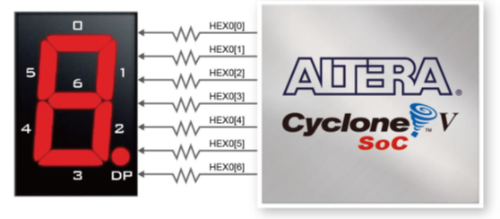
Below there is an example of the output signals HEX (one for each 7 segment display) and the configuration of each of them to display the word ““OPEN”.
module example
(
output logic [6:0] HEX0, HEX1, HEX2, HEX3, HEX4, HEX5
);
// OPEN

HEX5 = 7'b1000000;
HEX4 = 7'b0001100;
HEX3 = 7'b0000110;
HEX2 = 7'b0101011;
HEX1 = 7'b1111111;
HEX0 = 7'b1111111;

endmodule