Integration and Assembly Language
Introduction
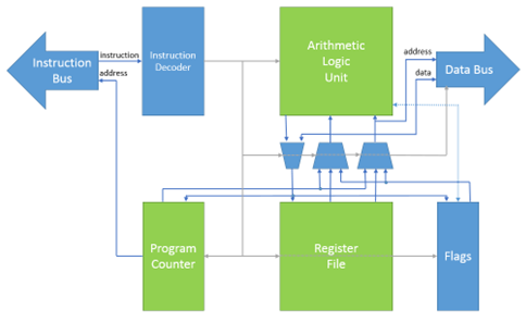
In this activity you will put your Arithmetic Logic Unit, Program Counter, Register File and VGA controller together to form a processor like this:
Setup
Create a Quartus project with the name HighRiscSystem, then download the zip file ‘HighRiscSystem.zip’ and extract files in the same folder of your HighRiscSystem project. Use the HighRiscSystem file as the top level module. You will need to add the following files to the project:
- HighRiscProcessor.sv
- HighRiscSystem.sv
- InstructionSet.sv
- RomBlock.qip
- RAM.qip
- Your ProgramCounter module
- Your RegisterFile module
- Your ArithmeticLogicUnit module
- Your VgaController.sv
The .qip and .mif files are used to describe memory blocks in a way that makes it easy to download new files to them. Import the system_soc.qsf file to set the pin locations including KEY 0 which is the reset.
This processor system has the following memory and I/O devices:
| Module | Address | Size | Bus |
|---|---|---|---|
| Program Memory | 0 | 4000 | Instruction |
| Data Memory | 0 | 4000 | Data |
| VGA display buffer | 4000 | 4000 | Data |
Switches SW0 - 9 |
C000 | 1 | Data |
LEDs LED0 - 9 |
C200 | 1 | Data |
Activity 1 - Test your modules in a processor
Add your ProgramCounter, ArithmeticLogicUnit, RegisterFile and VgaController modules to the project and build the project. If there are any issues, fix them by changing your files only. DO NOT modify the files downloaded from Moodle. Once compiled, download your project to the FPGA. The text file ‘switchToLEDs.txt’ contains the assembly code that has been loaded into the Program.mif file, which copies the values from the switches to the LEDs. In order for this program to work properly, all your modules (ProgramCounter, ArithmeticLogicUnit, RegisterFile and VgaController) should be fully working.
In the zip files downloaded from Moodle, you will also find the following examples programs in assembly language and their corresponding files .mif (assembled code or machine language):
- switchToLEDs.txt: reads the switch values and copy them to the LEDs
- rotateLeftLEDs.txt: reads the switch values, rotate them to the left and copy them to the LEDs
- addTwoValues.txt: adds an immediate value and a value from the switches
- delayLEDBlink.txt: implements a delay using a loop to switch on and off an LED
- saveDataInMemory.txt: performs arithmetic operations and stores the result in the Data memory
- readDataFromMemory.txt: reads data from the Data memory, performs operations and stores the results in the Data memory
- readAndDisplayPicture.txt: reads the Data memory to load a picture and display it on the monitor of the PC
Once your microprocessor is implemented in the FPGA, try the programs from the list to check the correct functioning of your system.
You need to load in the Program memory the .mif files as explained in the lecture on week 9 (Thursday 2nd December 2021).
If you did not attend the lecture, then watch the recorded lecture available on Moodle.
Activity 2 – Assembly language for the HighRisc microprocessor
Below you can see the assembly code of the example program switchToLEDs.txt, which copies the switch values to the LEDs.
// Switch and LEDs example.txt
//
// Assembler test - load switch inputs to LEDS
// U M.H.
// 01/12/21

LIL R0, 0 // Set R0 to the address of the switches (0xC000)
LIU R0, 0x38
LIL R1, 0 // Set R1 to the Address of the LEDs (0xC200)
LOAD R2, (R0) // Get the switch values to R2 - Load instructions must be
// done twice
LOAD R2, (R0)
STORE (R1), R2 // Copy R2 to the LEDs
This program in assembly language in processed by the Assembler (Hra.exe) to convert this code into machine language (0s and 1s) and write it into Program.mif file, which is the program that will be loaded into the program memory and executed by your microprocessor.
The format of the instructions in this assembly language and microprocessor is as follows (for more details see the ISA of this microprocessor):
<Opcode> <Destination>, <Source> // This is a comment
For jumps the format is as follows (for more details see the ISA of this microprocessor):
JR <condition to jump>, <Offset value> // This is another comment
The JR opcode causes the offset input of the program counter to be enabled. For this opcode, the condition is one of:
C– The carry flag is setZ– The zero flag is setN– The negative flag is setP– The parity flag is setV– The overflow flag is setNC– The carry flag is not setNZ– The zero flag is not setA– The jump is always taken
The offset is in the range +255 to -256. Note that the offset is relative to the NEXT instruction address.
Also note that this processor has a “delay slot” this means that the instruction that follows a jump (or other operation that changes PC) will execute and then the jump will occur.
For the LOAD opcode, the source should be bracketed to indicate that the register holds the address of the memory location to load into the destination.
Note also that all LOAD instructions must be issued twice.
To account for delays through to the data memory.
For the STORE opcode, the destination should be bracketed to indicate that the register holds the address of the memory location in which the source should be stored.
For other opcodes the opcode is as described in the Instruction Set Architecture (ISA) document provided in the Coursework Activity 3.
The source and destination are register names: R0 to R62, PC (program counter) or FL (flags).
How to run the Hra assembler
To run the assembler to generate the program (Program.mif) from the assembly code (e.g., switchToLEDs.txt) do the following:
- Open a command window
- Change to the directory where you have your project and the assembly code
cd <project_path> press Enterremember to use (“ ”) in case you have spaces in your project path - Type the command:
Hra -i <InputFileName> -o <OutputFileName> –m 0xFFFF
Set InputFileName to the name of your source code in assembly language, set OutputFileName to Progam.mif, which will be loaded into the FPGA when you compile your project in Quartus.
Activity 3 – Display a picture in the monitor of the PC
In the files downloaded from Moodle, there is a Christmas tree picture, a DataPicture.mif and a ProgramReadAndDisplayPicture.mif file. DataPicture.mif contains the data in hexadecimal format of the picture, and ProgramReadAndDisplayPicture.mif contains the machine language to load the data and display the picture in the monitor. In this activity, you will need to do the following:
- Load the program ProgramReadAndDisplayPicture.mif in your microprocessor
- Load the data DataPicture.mif in your microprocessor
- Make sure the VGA cable is connected from the FPGA and the monitor, and select the VGA input source in the monitor
IF (picture displayed in the monitor == True)
    Congratulations, now you are a SystemVerilog ninja!
ELSE
    Check your modules but DO NOT modify the files of the HighRiscSystem downloaded from Moodle
Optional activity just for fun!
Do some changes to the assembly code to manipulate the bits of the picture displayed in the monitor. For example, you can try any of the following:
- Read the switches of the FPGA and depending on their value, display only one colour channel (Red, Green or Blue) of the picture.
- Add a delay (e.g., 1 sec delay) and make the Christmas tree blink.