Single-Wavelength System
This section will provide you with the necessary information to use the analogue components to measure heart rate.
Step 1: Read the Datasheets
Read the datasheets for the analogue system components mentioned in the Equipment section of this lab script.
Step 2: Design the Circuit
Using what you have learnt in Circuit Theory, design a circuit that involves an emitter (LED) and receiver (phototransistor). A video introducing the operation of phototransistors can be found in the Additional Resources section at the bottom of this page.
A filter can be designed to remove any high frequency background noise that may be present to improve the readings from the receiver. You may wish to use OrCAD to simulate the circuit and verify its operation before testing it.
Step 3: Build the Circuit & Check the Voltage Range of the Output
You are encouraged to use the lab bench equipment to view the circuit output before reading and processing it using the Arduino. If your circuit is functioning correctly, you should get a signal that looks similar to Figure 1 in Intro to Pulse Oximetry.
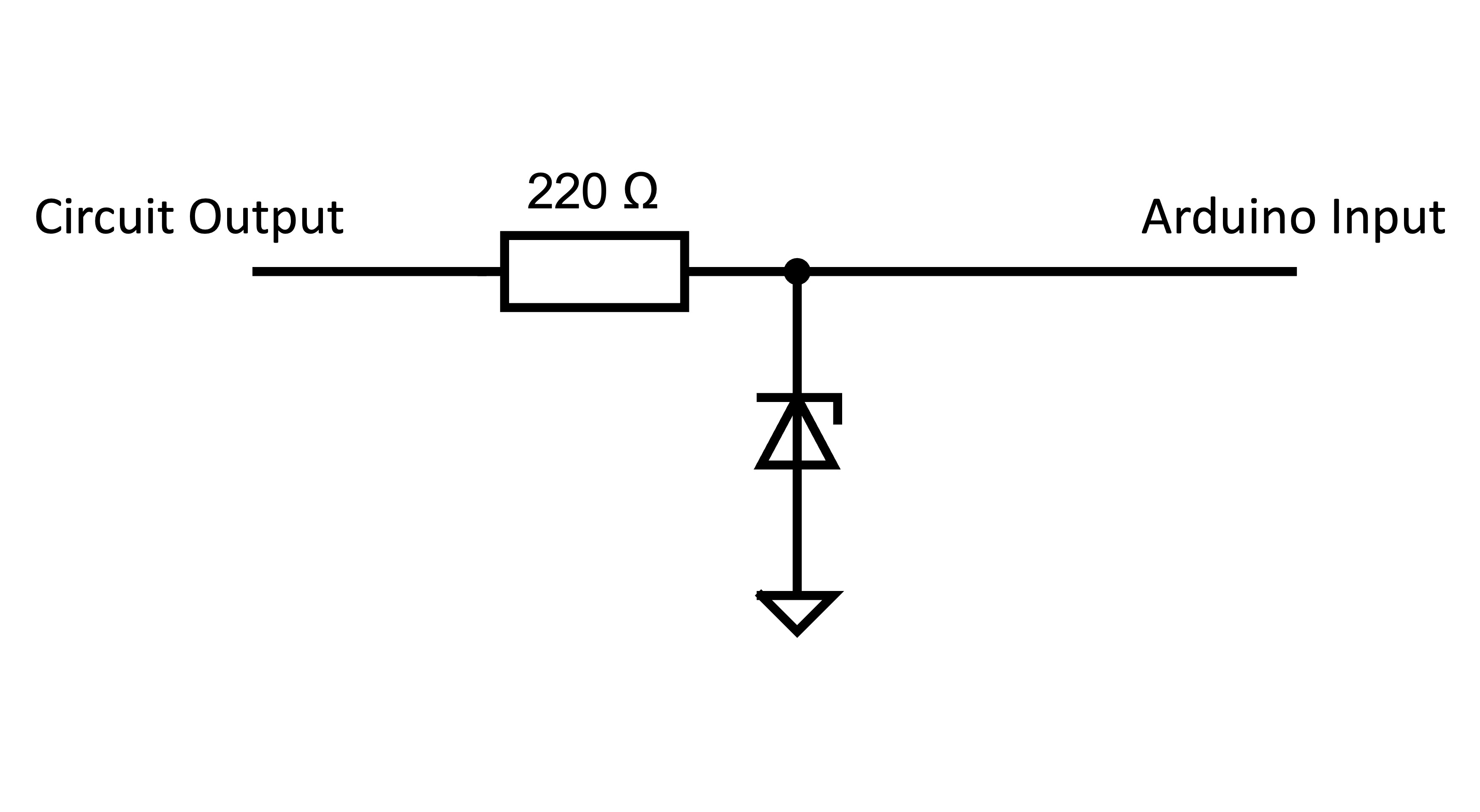
Arduino Protection Circuit
Protecting the Arduino from voltages over 3.3 V is crucial because higher voltages can damage the microcontroller and other components. The Zener diode is used for this protection; it limits the voltage to a safe level by conducting excess voltage away when the threshold (breakdown voltage) is exceeded, thus preventing damage to the Arduino. A video about zener diodes is available in the Additional Resources section.
Step 4: Use the Arduino to Calculate the Heart Rate
In this step, you will use the Arduino to calculate the heart rate. This involves detecting heartbeats, measuring the time between them, and then calculating the beats per minute (BPM).
A) Implement an algorithm to detect the beats
The simplest approach is using a threshold value: when the phototransistor reading exceeds this threshold, a heartbeat is detected. However, other peak detection approaches may be used.
B) Measure the time between beats
You may find the millis() function useful at this stage.
C) Calculate the Heart Rate
To calculate the heart rate in beats per minute (BPM), you can use the formula below. Remember to pay attention to units.
\[\text{BPM} = \frac{1}{\text{Time Between Beats in minutes}}\]D) Improve Reading Accuracy:
The direct BPM calculation from each heartbeat might lead to fluctuating readings due to minor variations in heartbeat or sensor noise. To achieve a more stable and accurate BPM reading, consider the following:
- Averaging BPM Values: Implement an averaging method, such as storing several recent BPM calculations and computing their average.
- Adjust Sampling Rate: Experiment with different sampling rates for a balance between responsive and stable BPM readings.
- Calibration and Testing: Regularly calibrate and test your system against the commercial heart rate monitor.
- Handling Edge Cases: Develop logic to handle unusually high or low heart rates accurately.
Additional Resources
Please note that the circuit in this video is detect whether or not the phototransistor is detecting light. This is NOT what you are trying to do in this project. Instead, you want to accurately detect the fluctuations in the measured signal.