--------- multipitchclimbing.com ---------
|
This site presents the images from the ebook High: Advanced Multipitch Climbing, by David Coley and Andy Kirkpatrick. In order to keep the cost of the book to a minimum most of these were not included in the book. Although they work best when used in conjunction with the book, most are self-explanatory.
Please use the following links to buy the book: Amazon USA (kindle) / Amazon UK (kindle) / itunes / kobo |
|
Contents 1. Fall Factors / 2. Dynamic Belaying / 3 The 3-5-8 Rule / 4. Belay Device and Rope Choice / 5. Forces Depend on Angles / 6. Failing Daisies / 7. How Fast Do You Climb? / 8. What is a kN? / 9. What is a “Solid” Placement? / 10. A simple mathematical model of a climbing rope / 11. The problem with high energy falls |
|
In this chapter we expand on the basic idea of fall factors to account for rope drag, look at testing data from Petzl and Beal on real-word falls, consider if the angles between the arms of a belay really matters that much, look at how your daisy might kill you, introduce a unit of climbing speed (the Steck), discuss what the “kN” on the side of your carabiners means, present one way of defining just what is a solid placement and introduce a simple mathematical model of a rope. |
1. Fall Factors
|
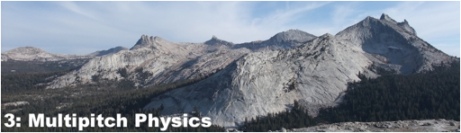
The longer the fall the more energy that needs to be absorbed by the rope. The fall factor provides a useful way of distinguishing between falls of equal length (and therefore equal energy) but that have different amounts of rope out to soak up the energy of the fall. The lower the fall factor the less force on the top piece, the climber and the belayer. Fall factors of 1 or more need to be avoided, as huge forces will be involved and they can be very difficult to hold.
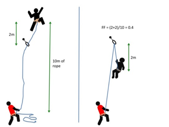
If there is a lot of friction from the runners or the lip of a roof, much of the rope will not be able to fully engage in absorbing the energy of the fall. Thus the effective fall factor will be higher than the fall factor calculated in the normal manner. The effective fall factor is defined as the fall factor that generates the same force as the real fall. For example in a real FF=0.5 fall friction might mean the leader experiences the same force as normally associated with a FF of 0.75. Hence the EFF is 0.75. It is worth realising that normally if the EFF for the leader is higher than the FF, then the EFF for the second will be lower than the FF. |
|
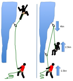
The fall factor is found by dividing the distance fallen by the length of rope out. Here the fall factor is 4/10 = 0.4. For a more in depth discussion of fall factors see http://wallrat.com/PDF_Files/forcesinleadfalls.pdf |
Effective fall factor (EFF).
|
The following images show the implication of the EFF displayed as a mathematical model which clearly shows how much each section of rope can help in reducing the forces on the leader. The sections nearest the second are seen to do little, with possibly one tenth the absorption per metre of rope as the section nearest the leader. |
|
|
|
|
|
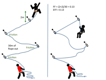
In the case of carabiners not far off-line, friction at the carabiners causes the effective fall factor (EFF) to be give approximately by: EFF=H/(L0+0.63L1+0.49L2+0.37L3+0.29L4+0.225L5) |
With carabiners clipped in line but with rubbing points against the rock, we have: EFF=H/(L0+0.52L1+0.33L2+0.19L3+0.11L4+0.06L5) |
|
The above images are from Beal and illustrate well the impact of friction in the system. (http://bealplanet.com/sport/anglais/facteurdechute.php) COPYRIGHTED IMAGES. For example, if L1..5 = 1m, and H (the distance fallen) = 2m, then the fall factor is 2/6 = 0.33; whereas, with the situation shown in the right hand image the corresponding equation gives an effective fall factor of 0.90 – a relatively serious fall. |
|
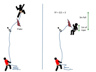
In exceptional circumstances the fall factor can be greater than 2. Here the rope fell down behind a flake and jammed as the climber fell, leaving only 1m of rope to absorb a 3m fall. |
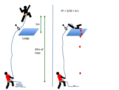
A low fall-factor doesn’t always mean a safe fall: falling off is only safe if there isn’t anything to hit.
|
Giving to the fall, rather than fighting it can reduce the peak force, making the experience better for both leader and second. In particular, this reduces the violence of any swing into the wall. Even on a multipitch route it is possible to give a dynamic belay by moving from one side of the anchors to the other or jumping up slightly, or using a chariot belay. |
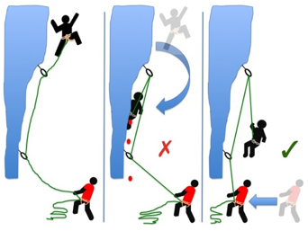
The use of dynamic belaying can stop the leader from flying into the wall and hence protects her ankles.
|
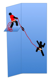
Due to the friction at the top (and other) pieces the second will not be exposed to as much force as the lead climber, and the force on the top runner will be less than twice that on the lead climber. The ratio between the forces will depend on the situation, but 3:5:8 has been the working assumption for many years. |
The very approximate 8/5/3 rule.
|
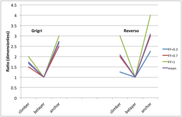
Petzl have done a small series of tests on the forces experienced during real falls (i.e. using a human as the test mass) for various fall factors. The results seem to support the 8 / 5 / 3 rule extremely well, at least when a Grigri is used (the mean experimental ratio was 8.2 / 5.2 / 3) – with a Reverso the data is more scattered. |
|
|
|
Ratio of the force on the climber and anchor to that on the belayer for a series of real falls with fall factors of 0.3, 0.7 and 1 (the lines are just a guide to the eye). Data from http://www.petzl.com/files/all/product-experience/SPORT/R32-PE-CORDES-EN.pdf |
4. Rope and Belay Device Choice
|
Devices like the Grigri are often criticized for putting more force on the top runner as they don’t allow the rope to slip. On the other hand, unless the top piece is poor, this might not matter in comparison to the second losing control of the rope and dropping the leader after twelve hours of belaying in the sun. |
|
Clipping in line with no rubbing points below the top runner. Fall of 8 m. |
Clipping 5 slightly off-line runners in 19 m of ascent, with no rubbing against the rock. Fall of 8 m. |
||
|
|
|
|
|

|
Clipping 5 slightly off-line runners in 19 m of ascent, with some rub-points. Fall of 8 m. |
Overhanging passage with a rub-point on the roof lip - Fall of 8 m. |
||
|
|
|
|
|
|
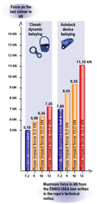
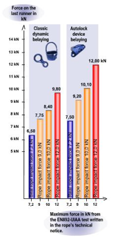
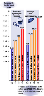
Although this is a complex issue and further testing is required, the above images from Beal indicate that belaying with a locking device such as a Grigri, does increase the force on the top runner considerably, however I have yet to get sight of the experimental protocol that is behind these results. It also confirms that there is a relationship between the impact force a rope places on the system in the UIAA test (i.e. for a very harsh fall) and more common falls. This suggests that low impact rated ropes do indeed offer advantages in common situations. (http://bealplanet.com/sport/anglais/facteurdechute.php) All images COPYRIGHTED. The results from Petzl shown below indicate something similar. Data from http://www.petzl.com/files/all/product-experience/SPORT/R32-PE-CORDES-EN.pdf |

|
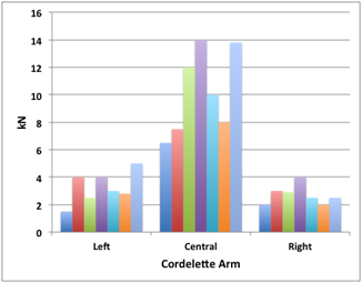
Forces (in kN) on the climber, belayer and top piece for a series of real falls. Forces are slightly higher with a Grigri for the climber and belayer, but only slightly. The main difference is on the force on the top piece. This doesn’t mean a device like a Grigri is a poor choice for trad. Often ensuring the fall is held is more important than the forces. |
5. Forces Depend on Angles
|
It is sometimes a good idea to link pieces together in opposition, either on the lead or at the belay. This can increase the forces on the pieces, but this will be worth it if it ensures the pieces stay in. Although some degree of load sharing might be possible by using techniques such as the sliding-X, more often than not it is more important to use the approach to stop a piece being lifted out, or to stop the belayer falling off the stance if one piece fails.
Many climbers understand that as the angle between the arms in a belay increases the load increases on each arm, they fail to understand that if the angle is small any sideways movement will dramatically increase the load on one arm. This suggests that small angles are not in reality optimal, force-wise.
A consideration of angles is also important when thinking about the direction the belayer will be flung in if the leader falls. If the belayer is pulled sideways, rather than up, the normal dynamic effect the weight of the belayer produces will not be present, and the fall will be more aggressive.
Another time to thing about angles is when assessing the swing the leader or second might be exposed to if they fall whilst climbing. The force with which they smash into a corner will greatly depend on the angle between them and the nearest runner. |
|
|
|
|
|
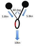
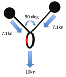
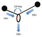
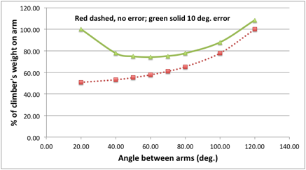
As the angle between two pieces increases the forces on the pieces increases. However, this doesn’t mean that large angles should not be created if they are the only timely option. Also the above is very much theoretical. In reality, the direction of the load is unlikely to always be straight down. Consider a real stance: If the last runner below the belay is to one side, or the belayer is hanging to one side, or the leader and second move around once they are at the stance and re-racking, then the direction will not be straight down, and might be constantly changing. The following graph compares the theoretical situation (as presented in the above diagrams for a non-sliding powerpoint), with what happens if at any time the direction of the load shifts to one side by 10 degrees. We see that if the angle between the pieces is small (20 degrees) then a slight movement of the belayer means one arm takes 100% of the load rather than 50%! This is the same load as when the arms are 120 degrees apart: a situation that most texts suggest we should avoid. We also see that unless you know that the load will always remain straight down the cliff, the best angle between the arms is probably 50 to 70 degrees. It also adds weight to the argument that the idea of ensuring load sharing between arms is over emphasised by many climbers. Redundancy is the key. The main advantage of a small angle between the arms is that if one piece fails, the belayer will travel less far before being saved by the remaining piece, and therefore might stay on the ledge.
|
||
|
|
|
|
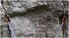
The direction of pull and the angle between pieces is important for more important reasons than the forces involved – the key is that the pieces MUST stay in. These two placements look fine when connected by a long sling (left), but not when connected by a short one (right) — now the direction of pull could easily unseat them. |
|
Angles in Powerpoints
|
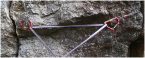
Results of seven pull tests on a symmetric three-armed cordelette anchor. The central arm is the shortest. It takes much more force than the others: clearly this is not equalizing. An ideal set up was used for this data, in the real world one arm will normally take most of the force because it is unlikely the powerpoint was built to equalise things for a leader fall. We can conclude that: One should worry less about angles and more about finding quality placements; adding more pieces might add redundancy, but is unlikely to improve the equalisation or reduce the force on the most loaded piece; however it might be worth avoiding one much shorter arm. (Data from J. Marc Beverly et al, Multi-point pre-equalized anchoring systems.) |
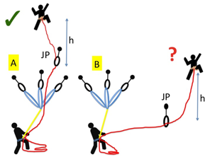
The angle between the leader and the Jesus piece
|
Rarely discussed in climbing is the difference between the actions of gravity and inertia. If the first piece is directly above the belay and the leader falls the belayer will be pulled upwards, but gravity will be acting on the belayer to limit how fast and far they travel. Hopefully this will result in a soft catch for both belayer and climber. This is a gravity-limited fall.
If however the first piece is off to the side but the climber has gained height after this piece or a subsequent piece, gravity will not slow the second when the leader falls. The result will be a more aggressive catch and the belayer might well be travelling fast when he comes tight on the belay and therefore let go of the rope. This is an inertia-limited fall, and will be at its most serious for the belayer if they are much lighter than the leader. In some drop tests reported by Petzl, they had to stop using a set up where the Jesus piece was off to the side as the belayer was suffering too much. Note: this is only occurs if the leader gains height. On a purely traversing pitch this is not an issue as the forces are low if there is a reasonable amount of protection. Nor is it likely to be a problem if the leader gained height after a long traverse with many pieces of protection in, as the drag of the rope on the rock will limit the force on the belayer. |
|
|
|
A: a gravity-limited fall. B: an inertia-limited fall. Be careful of the latter. Short traverses directly after a belay are a common problem. Using a chariot belay and one of the anchor pieces as the Jesus piece can help to solve this. |
The angle between the leader or second and the protection
|
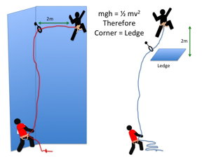
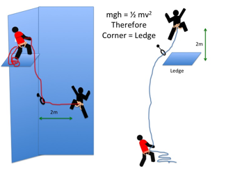
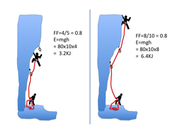
Another place where it is important to consider angles is if the protection is off to the side and a swing might end with the leader or second hitting something, usually the opposing wall of a corner. From high school physics we know that if the climber falls a distance h then their potential energy mgh will have all been converted into kinetic energy ½mv2 at the base of the fall. This is true whether the drop is a straight line or a swing. This means that a 2m (6ft) swing into a corner (with the protection at the same height as the climber) is the same as a 2m fall onto a ledge. A leader will try to do their best not to drop the second 2m onto a ledge, so they should try to not allow them to smash into a corner at the same speed. Often this situation can be avoided by the use of a second rope, or not placing protection at the base of a corner if using only one rope. The mental picture that probably needs to be encouraged is one of “corner equals ledge”.
A swing can easily be even more serious than a straight fall of a similar terminal speed. In a vertical fall onto a ledge you will hopefully land on your feet and your legs will bend to absorb the impact. In a swing the climber might impact the wall side-on, not feet first. This can lead to serious injuries even with small falls. (How would any of us fancy being dropped 2m horizontally onto a stone floor onto our ribs?) Accident data shows that a surprising number of climbing accidents are of this type, and possibly indicate that climbers don’t try take side falls as seriously as they should. |
A corner fall should be taken as least as seriously as a ledge fall if the vertical drop is identical.
The same is true for the second. i.e. they are “leading” as they approach a corner.
|
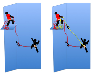
Right: limiting the consequences of a swing by using double ropes. The yellow rope reduces the height lost by the second as he falls, and hence through mgh = ½mv2 the speed he hits the corner. Although it could still be dangerous. Note: the yellow rope (i.e. the diagonal one) needs to be tight. |
|
|
|
It is worth using some maths to see how much difference this might make (we will ignore energy absorbed in the rope, and rope stretch).
Given that mgh = ½mv2 we know that v=root(2gh). As g=9.81, which is approximately 10, this gives the simple rule v=root(20h). i.e. if you fall h metres, you will be travelling at root(20h) metres per second when you pile into the ledge.
In the above drawing with a single rope, the height fallen will be given by the distance (L) from the corner. When double ropes are used the height fallen will be given by root(D2+L2)-D, where D is the height the belayer is above the second (or the height the first runner on the second rope is above the second).
Putting some numbers in we find the following:
For a single rope if the second is 5m out from the corner and the belayer 5m above them and there is (as shown) a runner in the corner at the same height as the second: D=5m, H=5m, they fall 5m, v=root(20x5) = 10m/s at impact and their kinetic energy will be 7.8kJ.
If two ropes are used then h=root(52+52)-5 = 2.07m i.e. the distance fallen has been more than halved. v=6.4m/s (nearly a 40% reduction) and their kinetic energy will only be 1.6kJ. This implies that energy-wise, using single ropes increases the energy of the fall (and that the climber’s body has to absorb) by a factor of nearly 5.
It is also worth considering what the numbers might have been if the leader had chosen to belay further up the corner. This makes no difference to the numbers if one rope is used and the lowest runner is still at the same height as the climber, as the distance fallen will be the same. However if two ropes are used (and the second rope is tight), then if the leader belays a further 5m up the corner (i.e. D=10), then the second will only fall 1.18m (that’s a massive improvement over 5m), v= 4.9m/s and the kinetic energy will be only 0.9kJ, i.e. an eight of the single rope case.
|
|
If you don’t have double ropes the consequences of a swing into the corner can be reduced by placing the first runner high rather than low. This might seem simple, possibly obvious, but most leaders seem to forget the maths once on the hill. This won’t always be possible as the leader might need to protect herself when ascending the corner. |
6. Failing Daisies
|
Falling on a daisy or any lanyard is never a good idea as there is little to absorb the energy, so the forces can be very high. However, tests seem to indicate that using a rope-based lanyard (such as Beal’s Dynaclip) can reduce the forces involved compared to using a sling. |
|
Test |
FF |
Dynaclip |
Nylon sling |
Dyneema sling |
|
Impact force on system |
1 |
6.2 kN |
11 kN |
>15 kN |
|
Number of falls before failure |
1 |
>20 |
4-8 |
0-1 |
|
Impact force on system |
2 |
9.5 kN |
>15 kN |
>15 kN |
|
Number of falls before failure |
2 |
8 |
0-2 |
0 |
|
Comparison of the performance of rope- and webbing-based lanyards under test falls. Forces over 12 kN should be seen as highly dangerous. (80 kg drop mass; FF= fall factor; data from Beal. As the mass was presumably inflexible it is not clear how representative these data are of the true difference between these three possibilities when used in the real world.) |
|
One rainy afternoon in the pub we were reflecting on the film of Ueli Steck climbing the 1938 route on the Eiger in 2hr 47min. This is a speed of 900m/hr or 15m/min (50 feet per minute); a speed we termed 1 “Steck”.
Knowing this definition means you can usefully reflect on how fast you are climbing by working in units of Steck. If you shut your eyes and count slowly, 1001, 1002, 1003…., then 15m/min doesn’t seem that fast if the climbing is not near you personal limit and much of the protection in situ, i.e. the main thing that is being measured is body movement - test it at the climbing gym (wall) and you might find you can climb easy routes at 0.5 Steck. However when we use units of Steck to analyse our own performance on real rock climbs we quickly discover time must be evaporating somewhere.
For example, if a relatively easy, mainly bolted, 10 pitch, 300m route has taken you 4 hours (and we all know people who might take all day on such a route), you have been moving at a speed of 75m/hr. Which is only 75/900 = 0.08 Steck! Even if you allow for the fact that your second also had to climb the route, this is depressing. The thesis of this book is that although some of this time difference is because we are weak and we move our limbs more slowly than Ueli (and because we might have had to tackle a couple of crux pitches), much is because of the time spent messing around with the rope and other equipment. Hence if you can speed this, systems-based, element up you will gain much more speed-wise than you will trying to get stronger in the climbing gym. Most of us will never be able to pull the kind of moves needed to climb 5.14, or have the physical fitness and perfection in movement to climb the Nose on El Cap in 3 hours, but there is no reason not to be able to tie a clovehitch or re-rack the equipment as fast as anyone.
There are probably two parts to this speedup: (1) Having a good knowledge of what works, with a lot of alternatives in your toolbox of techniques, and (2) having practised the techniques in a safe environment until you are totally proficient.
Hopefully the book and these webpages will give you an idea about possible techniques, but in the end you will need to get out there with a stopwatch or a video camera and discover where you are wasting time. I know it sounds geeky, but taking the effort to produce a table or pie chart which includes every element - time spent climbing, placing gear, cleaning, racking, the length of time between when the ropes go tight and when the ropes are in the belay plate ready to bring the second up, etc. – will pay a huge dividend. |
8. What is a kN?
|
Climbing equipment is often marked with a label in kN indicating the maximum force it can take. A force is a pull or push upon an object resulting from its interaction with another object: forces only occur during the interaction between objects. There are two types of forces: contact forces and action-at-a-distance forces. In climbing we are interested in both; gravity is an action-at-a-distance force, a rock hitting your head provides a contact force.
Force is a vector quantity, i.e. it has both magnitude and direction. This is important as it is the direction of the force that is as likely to rip a stopper from the wall as the magnitude of the force. Direction is also important when it comes to flying climbers.
Newton’s second law states F=ma (force = mass times acceleration). So halving the mass (with all other things being equal) will halve the force (i.e. a light climber will provide a lower force and stress the system less); as will halving the acceleration. As mass isn’t a vector F=ma must mean that acceleration is also a vector. In SI units force is measured in newtons (N).
F=ma also applies if the acceleration is negative, i.e. a deceleration, and often it is ensuring this deceleration is as slow as possible that is used to limit the force on the system and the climber.
For a suspended object the other object in the interaction is the Earth, and the acceleration will be the acceleration, g, due to gravity, so F=mg in this case.
g = 9.81ms-2 (or about 10ms-2), so an 80kg climber, hanging from the belay will provide, F=mg = 80 x 10 = 800 newton.
An 80kg climber slowing from 54miles per hour (24m/s) in a fall (a speed that could be reached in 30m of free fall) to stationary due to a braking force from the rope of 3kN would decelerate at 38m/s2, i.e. nearly 4 times g. They would take 0.65s to stop and the combined movement of the belayer, rope stretch and slip, plus a little bit of slack, would be nearly 8m! A much great distance than most people think, and why you see climbers pile into the deck on safe climbs, (These numbers come from simply applying the equations of motion, and are therefore slightly simplistic.) |
9. What is a “Solid” Placement?
|
Although higher forces are possible, the maximum force on a placement under normal circumstances is likely to be no more than 12kN (as the force is limited by the rope, with the placement experiencing twice the force the rope does). A kN is not a unit most of us find natural, so one way of thinking about how strong a solid runner placement needs to be is to reflect on the static hanging mass that might provide 12kN. As F=mg, m=F/g = 12000/10 = 1200kg. This is the weight of a small car. So, if you want to judge what is meant by a “solid” placement, you should be happy hanging a small car from it and letting your children picnic underneath it.
|
10. A simple mathematical model of a climbing rope
|
We can use a little high school math to create a model of a climbing rope and use this to examine the likely forces is the system. (Thanks to Mark, The Ex-engineer, for much of the following). The model is a rough one, in part because it ignores and movement of the belayer or friction between the rope and rock, or the leader rolling/bouncing down the face rather than being in free-fall. It is based on a consideration of the data that comes with any climbing rope you buy.
Single ropes are tested under the following conditions (the UIAA test): - a test mass of 80kg - 2.8m of rope 'in play' - 0.3m of rope to the 1st runner, 'climber' 2.3m above runner with 0.2m of slack, giving an initial fall of 4.8m
The tests give three numbers which are prominently displayed on the rope’s packaging: · peak impact force on the 1st fall · % elongation on first fall · number of falls held by the samples tested.
A typical rope might have the following characteristics: · An impact force of 9.1kN for the first fall (which is well below the maximum allowable of 12kN) · It elongates 30% in the first test fall (well below the maximum allowable of 40%) · Finally it holds 7-8 falls before it either snaps or exceeds the 12kN impact force limit (well above the minimum of 5).
In the standard rope test, the fall factor is 1.71. It is tempting to assume that the forces increase in direct proportion to the fall factor (FF): double the fall factor and you double the force on the top piece (or the belayer, or the climber). However, forces don't increase simply with the FF. This is where the maths comes in. They increase in line with the square root of the FF. So If you double the FF, the forces increase by only 1.41. The corollary being that the FF would need to be reduced by a factor of four in order to halve the force. This comes directly from the basic physics: the energy stored in a spring (which is what the rope is) is proportional to the square of the force. So if you fall twice as far (with the same amount of rope out) the FF will have doubled and, via energy = mgh, the energy of the fall will have doubled, but the force will only have increased by a factor of 1.41. Or stated the other way around, the force increases inline with the square root of the energy the rope absorbs per metre of rope.
The next thing we need to consider is how a real climber compares to a steel 80kg test mass. This is because there is some “give” in the climber’s body when it flexes as the rope comes tight. There seems some debate about this, but the answer is probably that there is perhaps a 10-15% difference. So the test mass might behave more like a 90kg human than an 80kg one. However, by the time you start considering the weight of a standard climbing rack, harness, helmet, clothing etc. the differences are fairly minimal. If you do want to correct things for a 'real climber' who is much lighter of heavier than average it turns out that the forces are proportional to the square root of the weight (as again, energy = mgh and the force goes with the square root of the energy). This implies that a climber who is half the weight gives rise to more than half the force of the heavier climber.
The final thing we need to consider is how do we translate the forces on a climber to the forces on the top runner. If the carabiner on the top runner acted as a perfect pulley the force on the runner would be twice that on the climber. In the real word, due to friction, it is nearer 1.67 times.
So to analyse any hypothetical fall we simply consider how much we need to adjust for things not being the same as the standard test fall. For this we need to know: · The rope impact force (Fimp) and elongation (Elong) produced in the test fall (for our rope, 9.1kN, and 30% respectively). · W - weight of the climber plus kit (in kg). · Lf - length of the fall (before the rope comes tight; in m). · Lr - total length of rope in play (in m).
Using the fall factor we can then calculate a scaling factor (SF) to adjust for the true weight of the climber and the FF:
SF = square root (W/90kg) x square root (FF/1.71)
Where FF=Lf/Lr as normal.
We then use the scaling factor as follows:
Force on climber = SF x Fimp Force on top runner = 1.67 x SF x Fimp Rope stretch = SF x Elong x Lr
An example: A light climber (70kg with gear) falls off around 8 m up a route with their waist 2 m above the last runner. The fall factor is 0.5 which gives a scaling factor of Root(70/90) x Root (0.5/1.17) or 0.58.
Hence according to this simple model:
Force on climber = 0.58 x 9.1kN = 5.28kN Force on top runner = 1.67 x 5.28kN = 8.8kN Rope stretch = 0.58 x 30% x 8m = 1.39m
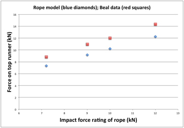
Because this model ignores many important elements, for example how hard the belayer can grip the rope, it is only an approximation designed to help climbers understand what is going on and the relationships between the important parameters. Just for fun I (DC) put the first fall described in the Beal diagram above (which described measured data from real falls) into the model for the five different ropes Beal used (i.e. only one runner, climber directly above runner, 7.15m of rope to the top runner, 4m of rope above runner to climber). I got the following graph for an 80kg climber (I used the data from the Grigri tests, as the model does not allow for slippage at the belay device).
Looking at the graph it would seem the model can represent some real world situations reasonably – in particular that the impact force rating stated on the rope’s packaging for a FF=1.71 situation does have relevance to more modest falls, with ropes with lower ratings producing less force on the top runner.
It is worth noting that one effect of the square root relationship is that even fairly small falls will still result in moderate forces. A pretty small fall (FF = 0.15) might result in a runner force of 50% of the rope’s impact force rating achieved during the standard test fall, yet a big fall four times larger (FF = 0.60) will only equal twice this.
Hence we can conclude that when it comes to runners, there isn't a massive different between small falls and big falls. If your gear isn't completely solid it is likely to fail regardless of how small a fall you take. |
11. The problem with high energy falls
|
The concepts of fall factor and effective fall factor are highly useful in thinking about how to compare one fall with another. However not all falls with identical fall factors are the same. For falls were the FF is small, a long and a short fall with the same FF will feel reasonably equal for both the leader and second (assuming the leader doesn’t hit anything on the way down). However once the fall factor is large enough for the forces to be great enough to pull rope through the locked off belay plate, the energy in the fall matters as well as the FF. This is because the rope is now not the only energy absorbing item: the belayer’s hands, the belay plate and the body of the belayer start to play a role. As energy = mgh we see that in energy terms a long fall with a high fall factor is even worse than a short fall with the same fall factor. The movement of the rope through the belay device and locker will create heat due to friction, and we experience this when an abseil device gets hot on a long descent. The movement of the rope through the hands however also creates heat.
The belay plate works as a force multiplier effectively multiplying the force the hand can apply to the rope by a factor of about 3. The corollary being that the hand must be offering about 1/3rd of the braking force and will suffer a corresponding rise in temperature. If enough heat is generated the skin will be damaged and the belayer may let go. So always be concerned by big falls and make sure you know you will be able to catch them. Belay gloves will stop you getting burnt, but tend to be slippier than hands, so it can be difficult to lock the rope off as effectively. A Grigri-like device provides an alternative solution. |
|
Two falls can have the same fall factor but differing amounts of energy. This will be important if the rope starts to slip through the belayer’s brake hand, heating the skin. |
Please use the following links to buy the book: Amazon USA (kindle) / Amazon UK (kindle) / itunes / kobo
v 19 November 2014
--------- multipitchclimbing.com ---------