Any errors let me know
Generate Tilt grain boundary
In this example only mirror tilts are considered initially...
The approach is first to generate the surface which is going to form one side of the boundary using the usual stackgen approach.
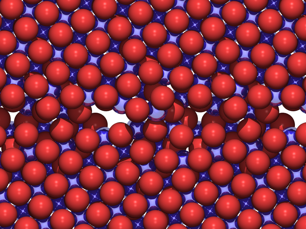
![]()
On running this, modify the staco0001_0001.out file
1. remove lines start (after bulk) --> surf and remove anal --> start
2. add lines after bulk (before start):
reflect
displace 0. 2.6 1.75 # this shifts the block2 by -2. 2.6 1.75 Angs in the x, y and z directions, note the default 2A shift in x.
The completed file should look something like:
![]()
Minimise Tilt grain boundary
Once this file is submitted it should minimise the boundary and generate a boundary, click on picture to obtain resulting fino0001.res file.
The summary file is also included here. It is sensible to calculate two energies associated with the grain boundary. Both energies can be obtained from running the original staco## file above. The first is the energy relative to the bulk crystal, called the grain boundary formation energy = Egb-Eb. In this case ( (-2225.475443) - (-2228.136823) = 2.66 J/m2. The second is the grain boundary cleavage energy = 2Es-Egb. In this case (2(-1111.245917)-(-2228.136823)) = 2.98 J/m2.
Add defect cluster to grain boundary
The final step is to modify the potentials so that they incorporate the impurities of interest and then add a neutral defect cluster. For charged defects consider using a Mott-Littleton approach, where the infinite dilution case is considered.
An example of a defect cluster is:
defect
ZR CORE vaca 0.4562659635774 5.0399950644665 11.2417704084624 5
W CORE inte 0.4562659635774 5.0399950644665 11.2417704084624
O CORE inte -2.4562659635774 5.0399950644665 11.2417704084624
O SHEL inte -2.4562659635774 5.0399950644665 11.2417704084624
ends
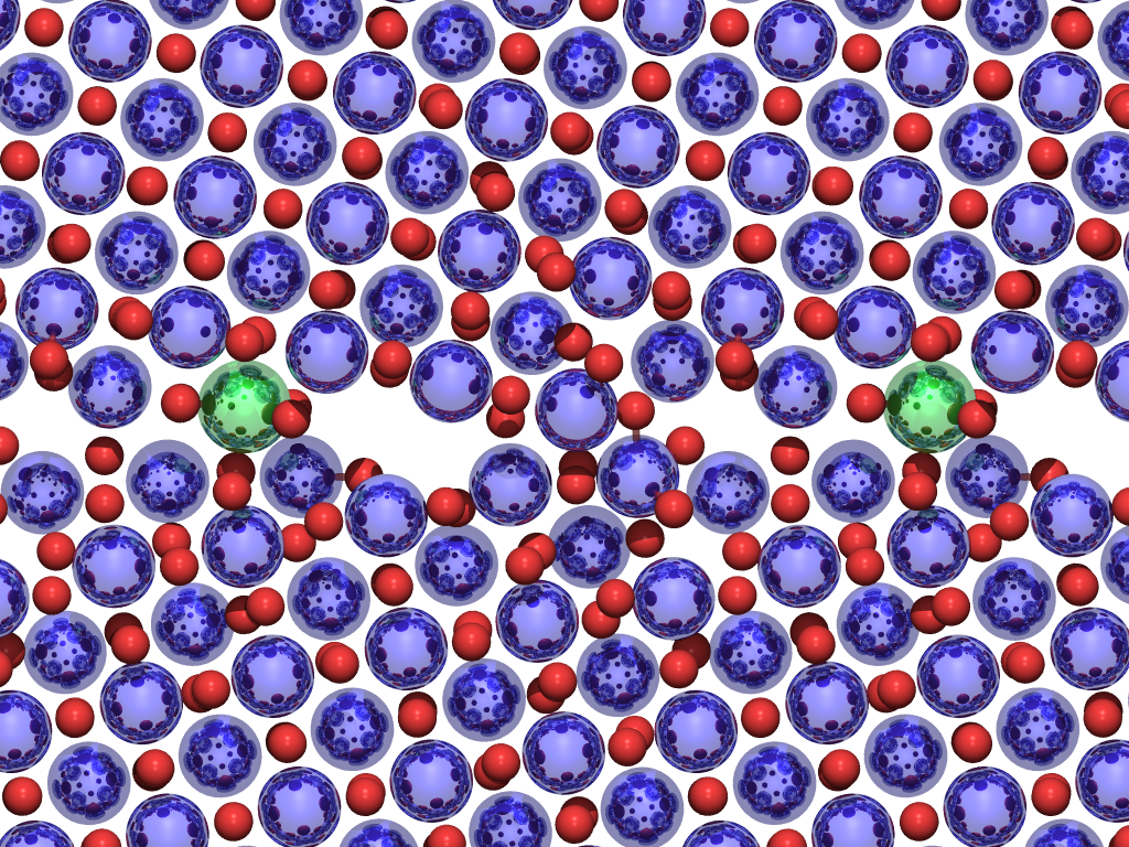
The resulting cell can be minimised, giving rise to the following fin###.res file.
The summary file is also included here. When calculating the energies from defective crystals, the key is to decide where the defects come from. If you imagine that the material is annealed with a given concentration of impurity or defect, the important property is the segregation energy. For this you need to know the energy cost for incorporating the defect in the bulk, e.g. from GULP, CASCADE or HADES. The energy difference between the defective boundary and the pure boundary per defect compared to the bulk defect energy per defect is the segregation energy (Eseg = (Egb_def - Egb_pure)/ndef - Egulp). This calculation can be performed with different values of ndef to give the segregation energy as a function of coverage. The defective grain boundary energy can also be evaluated (Defect gb = pure grain boundary + Eseg . nseg/Area). If intending to model the segregation as a function of coverage it is worth reading the Mackrodt and Tasker article (W.C. Mackrodt and P.W. Tasker, J. Am. Ceram. Soc. 72 (1989), p. 1576.). In addition, similar to the convention with point defect calculations, the energies can be compared to the lattice energies of bulk oxides and hence work out the solution energies.
Scan for optimum grain boundary structure and energy
In the example above the displace keyword, "displace 0. 2.6 1.75" displaces block2 relative to block 1. However, in the general case it is not possible to be sure of the best displace vector. Thus the file above can be modified to allow METADISE to perform a scan. This is achieved by simply replacing minimise by scan followed by frac ## on a separate line. The ## represents a fraction of the unit cell dimensions, so 0.2 will produce an equi-spaced 5x5 grid of points. A further constraint can also be added, conf, which keeps the y and z fixed and varies the distance between block1 and block2 or conh, which maintains constant height in addition to constant position. A modified file is also included here. Notice that to reduce the time taken for the scan the region sizes have also been significantly reduced, and the minimiation is only via a gradient method and not Newton-Raphson. The simulation will produce a file of energies to go in a sreadsheet called grid###.eng. The columns are y, z, height, energy. The height is relative to the initial height set by the displace keyword. Note that the lowest energy is the first one (at the origin), which corresponds to the y-z position set by displace:
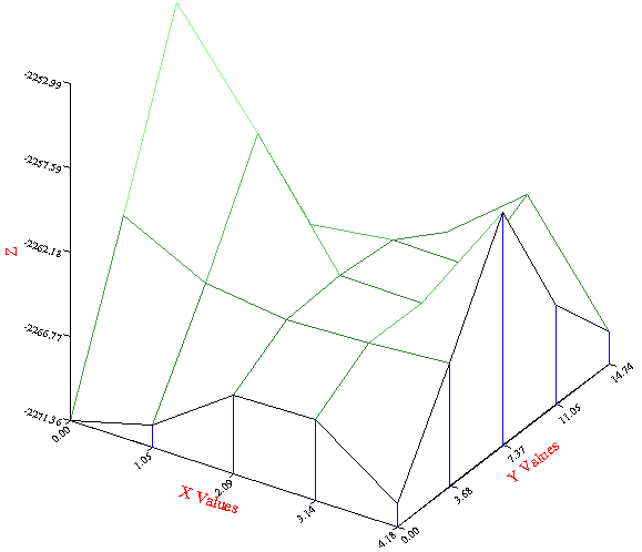
Note that the order is not the same as the displace keyword. Thus if using the scan results for the optimum displace vector, type "displace height y, z". In addition, watch out for local minima, it is not an issue here.
SC Parker