Engineering Drawings
Introduction
The aim of this lab session is to build on the work carried on in the previous week, to create engineering drawings of the assembly and one of the parts. Please note that the drawings generated in this lab are simplified and designed to introduce you to the drawing generation process.
Downloading the parts
The parts used in the drawing can be downloaded from moodle using this link. Please note that you must complete the previous lab first in order to create the assembly drawing.
Creating an Assembly Drawing
Below are refresher videos if needed.
Creating a Drawing File
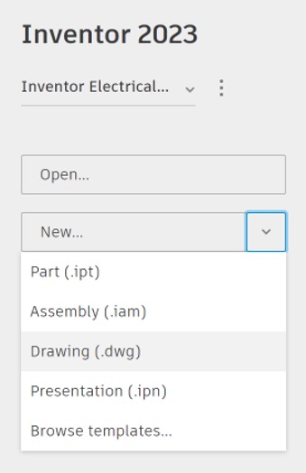
- To create a new assembly file, click on the arrow next to New and select
Drawing (.dwg)from the drop-down menu.
Edit Sheet Settings
The first step of creating a drawing is ensuring you have the right settings.
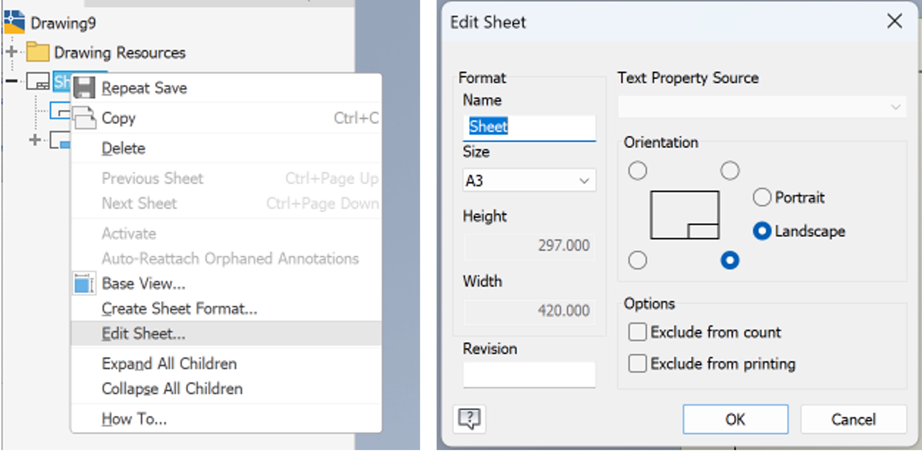
- Right click on
Sheetin the Model panel. - Click on
Edit Sheet. - For this example, make sure you are using an A3 Landscape sheet, as shown below.
Edit Style
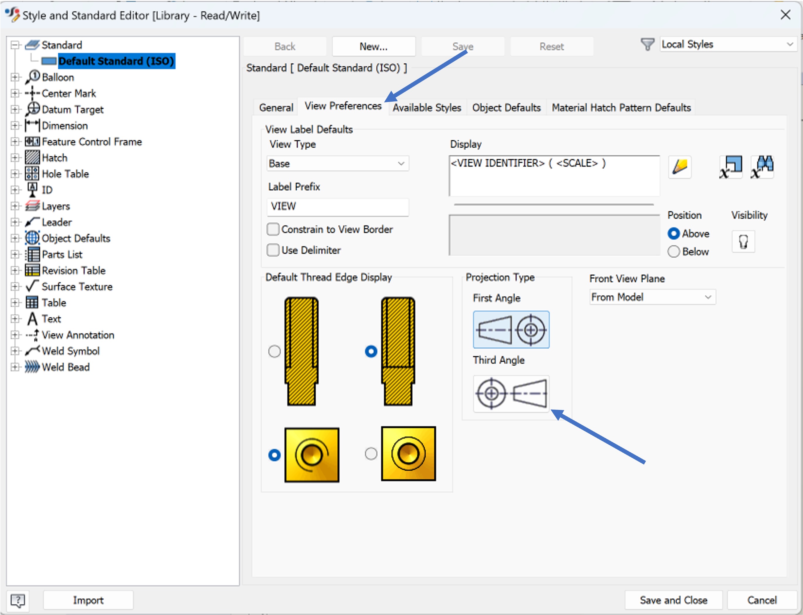
After ensuring the correct sheet size and orientation are chosen, the drawing style must be adjusted. Autodesk Inventor will automatically pick the ISO standard (discussed in the lecture). The standard defines the way different features are communicated in the drawing, such as hatching and line thicknesses.
The default setting is a first angle projection. However, this must be changed to a third angle projection by following the instructions below.
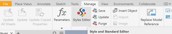
- Open the
Managetab. - Click on
Styles Editor.
- Ensure that the standard is
Default Standard (ISO). - Click on
View Preferenceson the right side to show a page that looks similar to below. - Within
Projection Type, selectThird Angle.
Add Drawing views
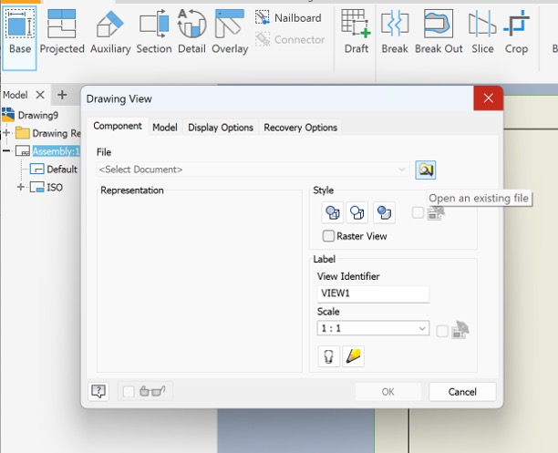
- Click on
Basewithin thePlace Viewstab - A pop up window will appear asking you to select the the file. Locate where you saved the roller assembly
- You have the option to select the scale. For this drawing choose 1:2, as it is the most suitable for the chosen sheet size.
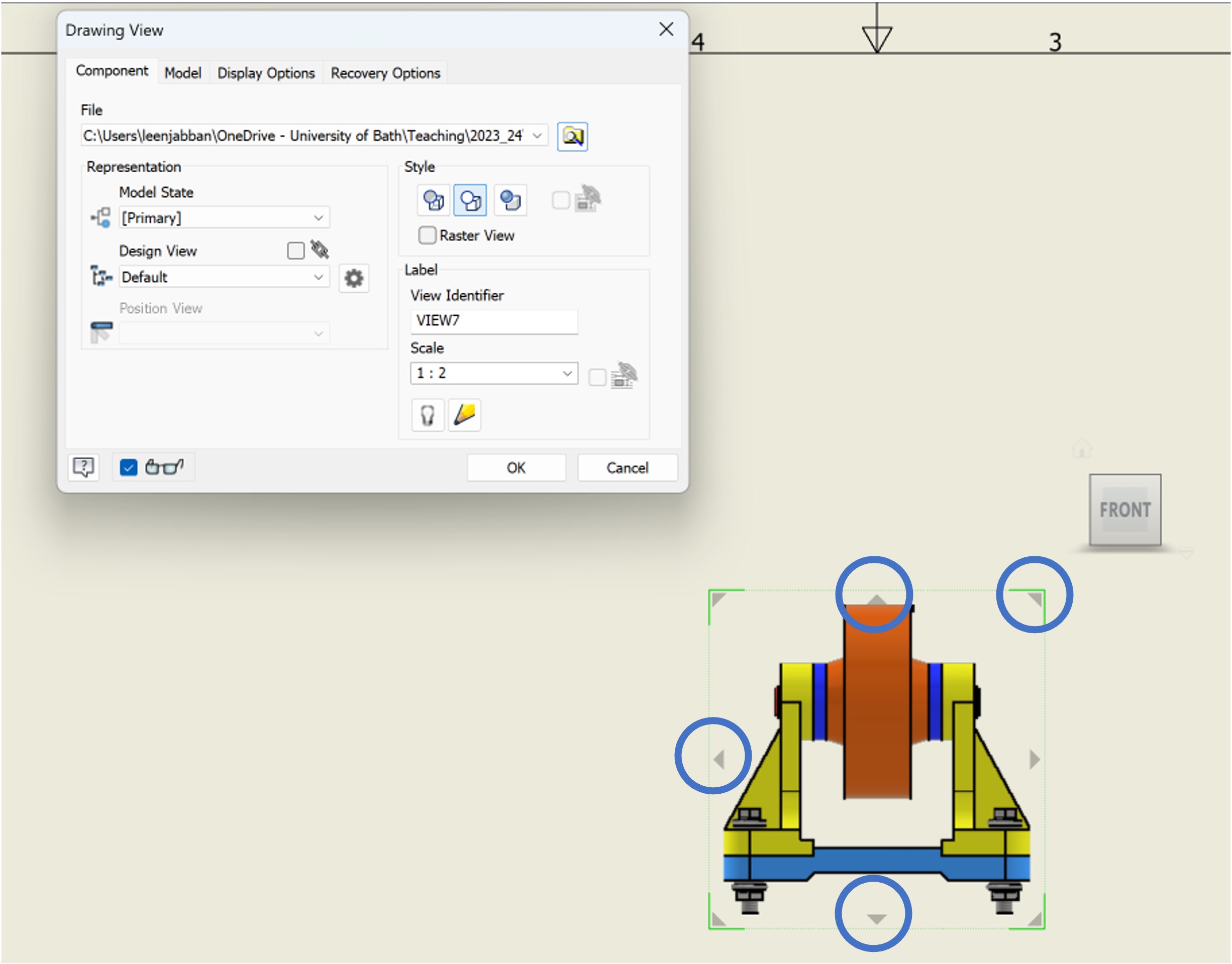
- You will notice a view of the assembly showing up on the sheet.
- You can use the arrows above, below, to the left and to the top right corner to add top, bottom, left and isometric views, respectively.
- Click
Okwhen you are done adding the views.
Instead of adding all the views in one go, you could use the Projected button (next to base). Once you click on that, you can select the base view of the part you wish to add more views of.
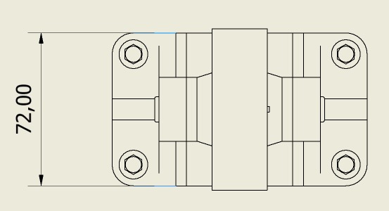
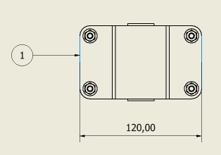
Add Overall Dimension
Unlike part drawings, Assembly drawings do not require intensive dimensioning. Instead, only overall dimensions are used to give the viewer an idea of how big the overall assembly is. To add dimensions:
- Click on
Dimensionsin theAnnotationtab.
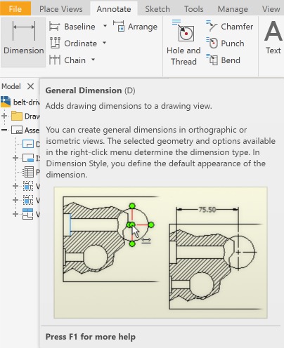
- Click on the edges you want to get the distance between.
- The dimension value will pop up, place it as appropriate by clicking on the location.
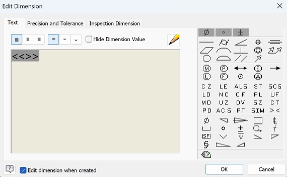
- An Edit Dimension pop up window will appear. This can be used to add symbols or edit the value of the dimension, as required. For now, just click
Ok.
- Repeat this step with a few more dimensions that provide the overall size of the assembly. An example is shown further in the lab script.
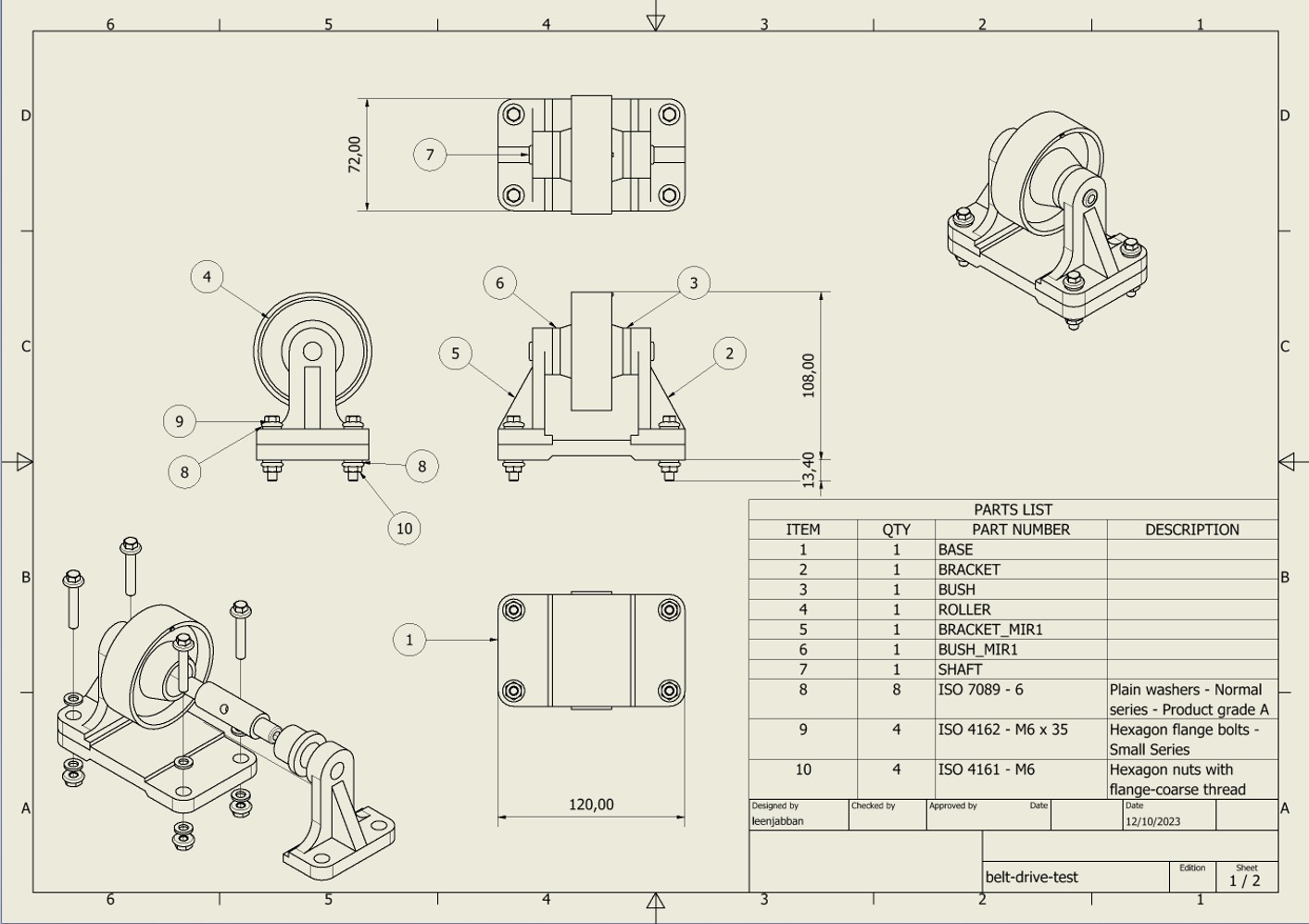
Add Parts List and Balloon Referencing
Because this is an assembly, a parts list and balloon referencing must be used to enable the viewer to know what parts make up to overall assembly.
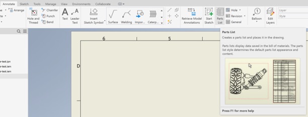
- Click on the
Annotatetab. - Select
Parts List.
- Click on one of the views of the assembly to automatically generate the part list for it.
- Place the table above the Title block, as shown below.
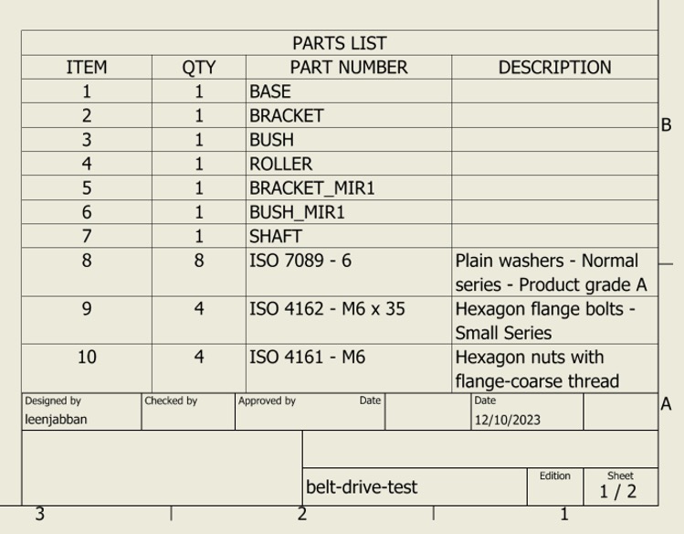
- The part list shows the item number for each of the parts. Inventor enables automatic mapping of the part to their item number in the table.
- Within the
Annotatetab, click onBalloon.
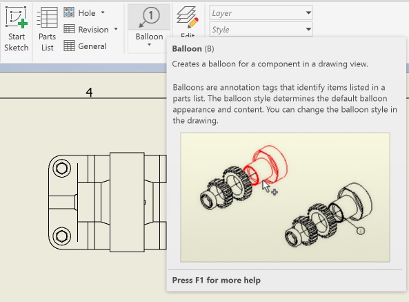
- Clicking on each of the different parts enables them to be labelled, as shown in the example below.
- Go over all of the parts ensuring each part is labelled once.
Add Exploded View
The previous lab provided instructions on how to create a presentation file, which includes an exploded view of an assembly. This exploded view can be add to the drawing to provide additional information, and show hidden parts.
- Use
BasewithinPlace Viewsto create a new view. - Instead of selecting the assembly, select the
.ipnfile created in the last lab. -
This will show the exploded view generated.
- By the end of this stage you should have a drawing that looks similar to the one below.
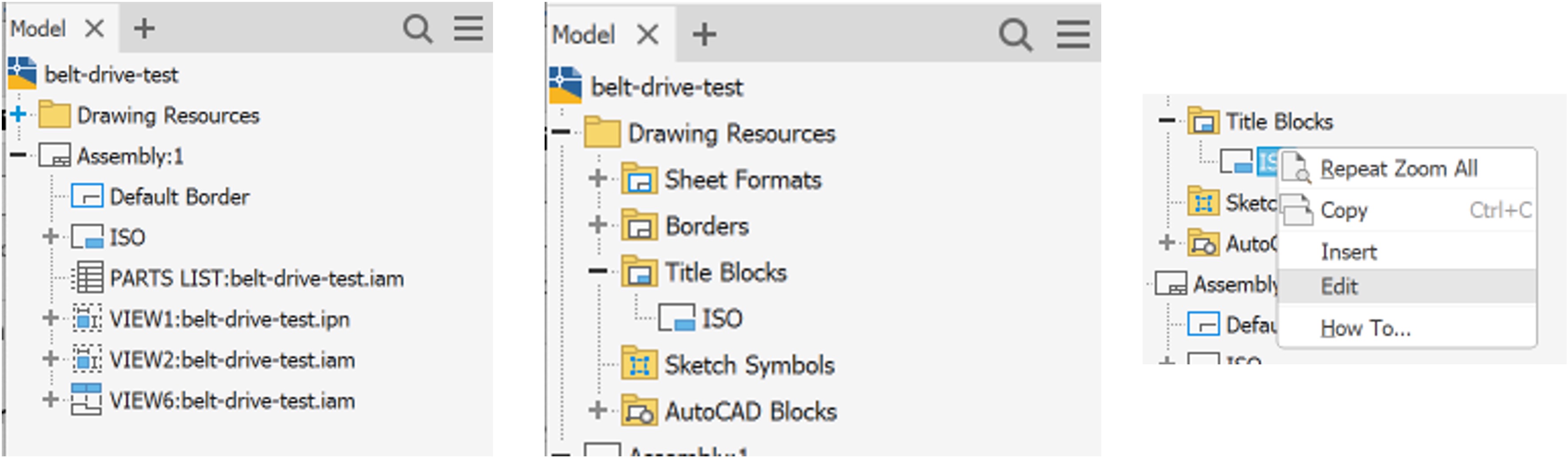
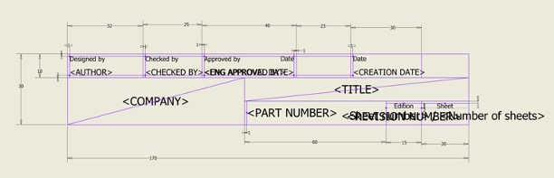
Edit the Title Block
You may notice in the example above that the title block is missing a few components such as the scale, units, and title of the drawing. Those can be edited as follows:
- Within the Model panel to the left, click on the
+next toDrawing Resources. - Click on the
+next to theTitle Blocks. - Right click on
ISOand clickEditto edit the title block.
- The title block will now show as a sketch.
- Double click on
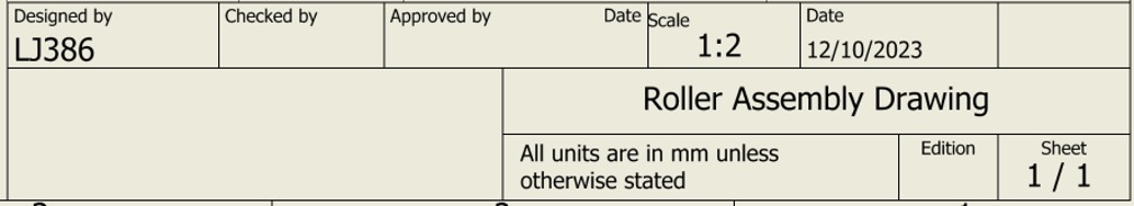
Author, and replace that with your username. - Add the rest of the parts of the title block either by editing parts or adding
Textfrom within theSketchtab. - The final title block should look something similar to the one below.
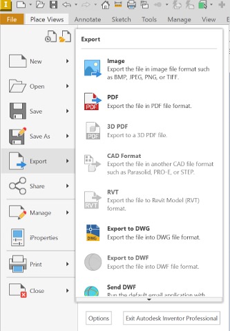
- Make sure you have saved your drawing.
- To export your drawing as a pdf, click on
File,Export, andPDF.
Creating a Part Drawing
Below are refresher videos if needed.
Creating a part drawing is very similar to an assembly drawing, with the exception of needing a part list and balloon referencing. Additionally, the level of detail is higher with much more dimensions needed.
- Create a new drawing file.
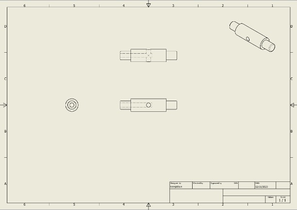
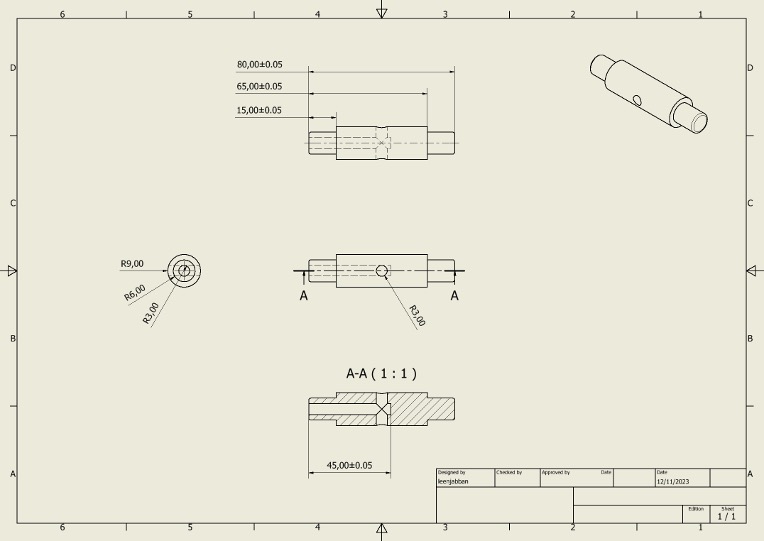
- Using
Base, add the four views shown below of the Shaft part.
Add Section View
While a section view is not strictly required in this drawing because the hollow section is visible using the hidden edges, we will include it as a learning exercise.
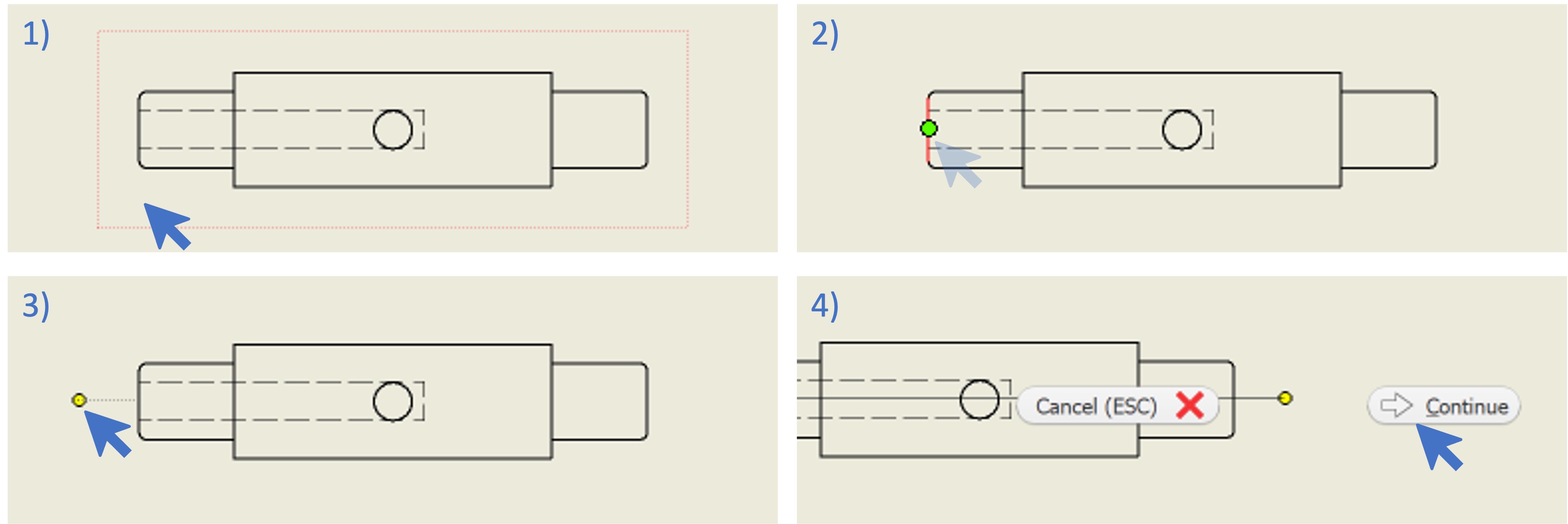
- Click on
Sectionwithin thePlace Viewstab.
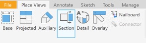
- Click on the view where you want to add a section (1).
- Hover over the first edge until the middle point is shown (2).
- Move the cursor keeping it in line with the middle point. A line should be visible as you do that (3).
- Click when you are sufficiently away form the edge.
- Repeat for the second edge.
- Right click to show additional options.
- Click on
Continue(4).
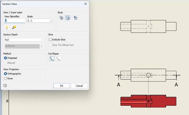
- A pop up window will show up, in addition to a coloured section view.
- Ensure that you are happy with the view identifier and scale within the pop up window.
- Move section view to a suitable location.
- Click
Ok.
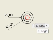
Adding Circular dimensions
- Click on
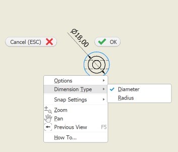
Dimensionwithin theAnnotatetab. - Click on the circular part you want to dimension.
- The dimension will show automatically, with the default set to the diameter.
- To change the dimension to the radius right click on the dimension.
- Click on
Dimension Typeand selectRadius. - Notice how the symbol changes to an R.
- Repeat for all the circular dimensions.
Adding Baseline Dimensions
We discussed in the lecture how the type of dimensioning affects how tolerances are implemented. In this example, we want the tolerances to be based on the distances to the edge of the shaft. To do that, we must use Baseline dimensions.
- Click on
Baselinewithin theAnnotatetab.
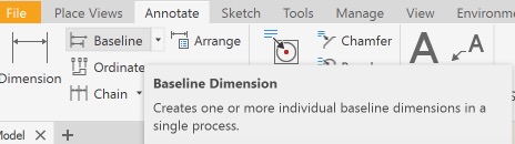
- Start by clicking on the reference edge (1).
- Click on the subsequent edges (2).
- Right click to display options and click
Continue(3). - Move the cursor above the part to show the dimensions (4).
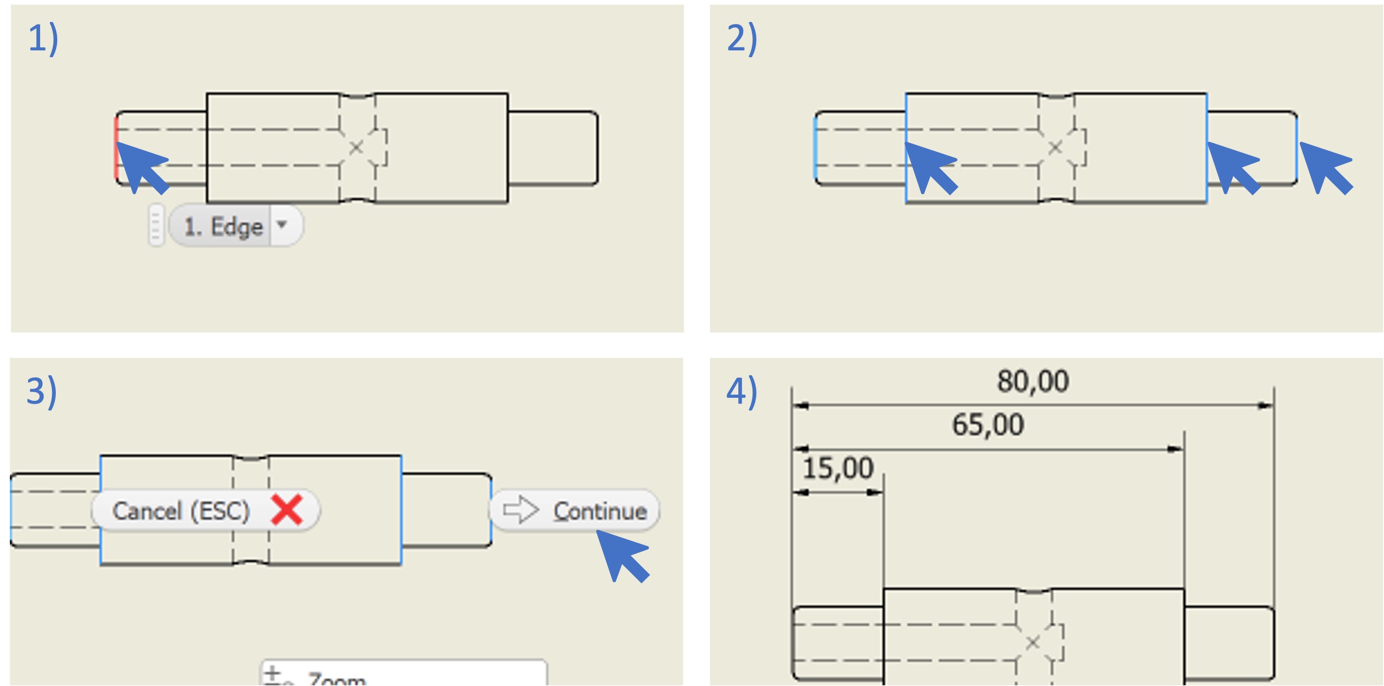
Adding Tolerances
The choice of tolerance value depends on the material, application and specific standard followed (amongst other). For this example, a tolerance of 0.05 mm is considered sufficient.
Tolerances can be added by editing the dimension values.
- double-click on the dimension you want to add the tolerance to.
- The
Edit Dimensionpop up window will show up. - You can use the Plus/Minus symbol to add it, followed by the tolerance value.
- You may notice that the space available for the dimension is no longer sufficient.
- You can re-arrange the dimension values by selecting the dimension you want to move.
- Hover over the dimension text until you see a four-sided arrow cursor.
- Click and drag the dimension to the desired location.
- Repeat for all the dimensions.
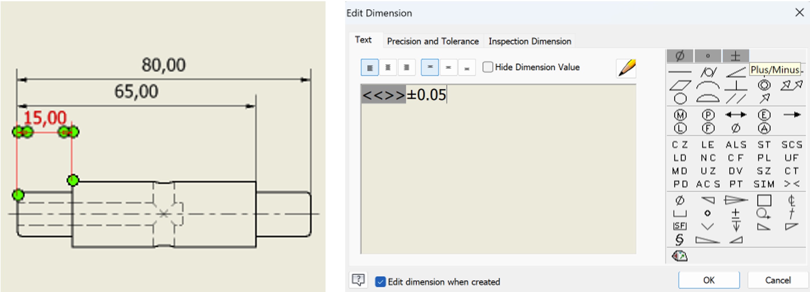
Adding Centre Mark and Centerline
Centre marks and centerlines are used to mark the the centre of circular shapes along the diameter and length, respectively.
- Click on the
Centre Marksymbol within theAnnotatetab.
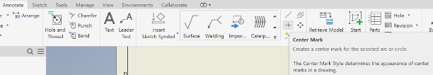
- Click on the target circle to add the centre mark.
-
Follow a similar process with the
Centerline(above the Centre Mark) to add the centerline along the shaft. Note that you need to select the midpoint between the edges of the shaft (hovering over the symbol will give you instructions on how to apply it). -
By this stage, the drawing should look similar to the one below.
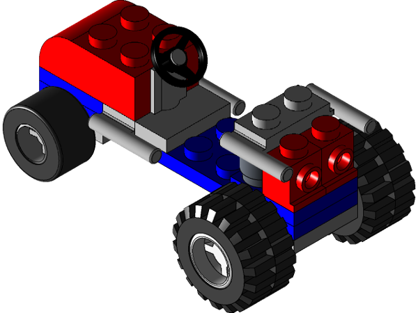
Application task
If you have completed the application task for the assembly lab, you can follow the same approach used above to create an assembly drawing as well as a part drawing.
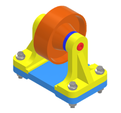
You can follow this link to download the parts for the application task. They are lego parts, enabling you to be creative in how you assemble them. However, below is a picture of a possible assembly should you wish to follow it.
References
[1] Roller files designed by ROHAN GUPTA [2] LEGO cad files designed by Hother - CPH Carpentry